Tuesday, December 31, 2013

FM Radio Station Microphonic Part 25

FM RADIO STATION MICROPHONIC PART 25

HOW DO YOU TRANSMIT VOICE WITHOUT A MICROPHONE?

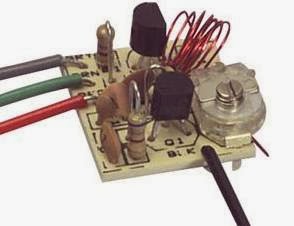
This is a two transistor circuit that makes up a wireless FM radio transmitter with a remarkable feature - it transmits voice without a microphone! 

It uses a floppy coil that moves upon receiving the vibrations from speech or other sources.


"This means it will vibrate when bumped and will even pick up sounds such as talking, music and footsteps and transmit audio just like a microphone.

Forget the phone lines as they are not needed for this example. Build the circuit and use 7 turns of thin wire on an 8-10mm pen and see how the coil picks up every sound in the room. Simply connect a 9v supply and the circuit starts broadcasting. The coil should be 6t and 3mm diameter, using 0.5mm enamelled wire."

Source
http://www.talkingelectronics.com/projects/Spy%20Circuits/SpyCircuits-3.html

FM Radio Station Notes Part 24

FM RADIO STATION NOTES PART 24

TUTORIAL: How Radio Waves are Produced
http://www.youtube.com/watch?v=aAcDM2ypBfE#t=186

FM TRANSMITTER
As a reference to going even smaller and more simple, this schematic shows possibly the most simple one transistor FM radio voice transmitter design, using a common 2N2222 transistor and only three capacitors and two resistors. There's only 7 electronic parts total to this assembly plus batteries and the antenna. A power on/off SPST switch should be added to the schematic.

Parts List
R1 Resistor 4.7K
R2 Resistor 220 ohms
C1 Capacitor .01uf
C2 Capacitor 33pf
C3 Capacitor 6.8pf
L1 Coil
Electret Microphone
2 - 1.5 Volt Battery

A slightly modified version is at this web site:
http://www.sentex.ca/~mec1995/circ/fmt2.htm
http://www.sentex.net/~mec1995/circ/circuits.htm

FM RECEIVER
The video also includes a schematic diagram for a very simple matching two stage FM radio receiver. This battery driven radio has only two transistors, amounting to 6 electronic parts plus batteries, switch and antenna.

Parts List
R1 Resistor 12K
C1 Capacitor 220n
T1, T2 Transistor BF199
C Variable Capacitor
3 Volt Battery
SPST Switch
Earphones
Antenna

BF199 transistor data sheet
http://pdf1.alldatasheet.com/datasheet-pdf/view/2947/MOTOROLA/BF199.html

MOST SIMPLE FM TRANSMITTER
The simple FM transmitter circuit shown above is a spinoff of this project. It uses only one resistor, one capacitor, one transistor and one coil. The article is found all over the web. It has no microphone but the coil is so microphonic that it will pick up noises in the room via vibrations on a table. The circuit does not have any section that actively tunes the frequency. The transistor turns on via the 47k resistor and this puts a pulse through the 15 turn winding. The magnetic flux from this winding passes through the 6 turn winding and into the base of the transistor via the 22n capacitor. This pulse is amplified by the transistor and the circuit is kept active. The frequency is determined by the 6 turn coil. By moving the turns together, the frequency will decrease.  The circuit transmits at 90MHz which is at the low end of the 88 to 108 MHz FM band. It has a very poor range and consumes 16mA.

http://www.circuitlab.org/2013/02/schematics-easy-build-rf-transmitter.html

http://skema-elektronik.blogspot.tw/2011_02_01_archive.html

http://circuit-diagram.hqew.net/Simplest-RF-Transmitter-circuit-diagram_4095.html

http://www.talkingelectronics.com/projects/Spy%20Circuits/SpyCircuits-1.html

This Google search link will find a lot more simple FM radio transmitter schematics and projects.


SIMPLEST FM TRANSMITTER
Here's another link to a project claiming also to be the simplest FM transmitter ever made.
http://circuitsdiy.com/the-simplest-f-m-transmitter-ever-made/

This circuit has audio input and needs only 2 resistors and 3 capacitors plus a coil and transistor.

"For input from low power output devices, such as mobile, computer’s sound card, the value of the unlabeled capacitor is 0.1 or 104. For higher wattage outputs, the value is 0.01 or 103. An optional microphone pre-amp can be also added in this circuit to enable it transmit voice directly."

ANTENNA
One idea to create the small transmitter antenna is to use a small wheel bicycle used spoke from a children's bike available from a bike shop probably for free.

How to Change a Dark Detector into an FM Transmitter
http://www.buildcircuit.com/fm-transmitter-and-dark-sensor/

A dark sensor can be converted to a simple FM transmitter using a similar schematic layout.

The dark sensor will light the LED as the output indicator. The transmitter substituted a microphone for the LDR.

FM TRANSMITTER
This FM transmitter is very sensitive and it has transmitting range of 30 meters with a 9-volt battery. Reducing battery power will reduce transmitter range.

Comments given at the link about the transmitter
The circuit may work but it relies on a “Q-factor” from the coil and capacitor in the tank circuit to produce a high voltage.

This high voltage gives the circuit a good range. Firstly the coil and capacitor should be near each other. The coil should not have long leads. and a 22n capacitor should be across the supply to give the circuit better performance. The value of C2 is too high. It should be 10p. The coil should be 5 turns. The electret mic should not be connected directly to the base of the transistor.

Monday, December 30, 2013

FM Radio Station Specs Part 23

FM RADIO STATION SPECS PART 23 
FM Radio Station statement of operating specifications, characteristics and purpose

Specifications 
Radio Type - Transmitter
Band - FM
Frequency Range - 88-108 MHz
Frequency Selection - tunable
Transmit power - under 100 mW
Range - desktop within room
Antenna - 1.75" diameter mini loop wire strand
Applications - hobby, school electronics, toy
Use - intermittent, testing, educational
Type - Personal Non-commercial
Power - 3 volts low power
Audio Source - voice electret microphone
Power source - battery
Typical Broadcast Duration- 30 seconds
Location - desktop
Size - pocket portable
Cost $4

Objectives 
* to fulfill the requirements of electronics design lab
* testing fm transmitter characteristics
* learning principles of broadcast radio stations

Applications 
* Transmit short range robot speech
* Classroom radio station project
* Electronics lab requirement
* Baby monitor
* Wireless pickup for guitar or ukelele
* Wireless microphone/KTV Singing
* Hobby or toy

Conclusion The micro FM radio station is a learning toy with short desktop range, a 1.75" antenna, and power under 100 milliwatts. No license is needed.

FM Radio Station Shielding Part 22

FM RADIO STATION SHIELDING PART 22
Whenever a capacitive or conductive source such as a human hand is in proximity or touching the radio station transmitter board, it can alter the signal and cause the circuit to drift, shifting the frequency.

To remedy this effect, install ground shielding throughout the radio station's enclosure. Form a continuous sheet of tin foil from a roll of kitchen aluminum foil used for cooking. Cover the inside of the front face plate as well. Make sure it contacts the sides to make a firm electrical connection without movement. Inside the cabinet, attach a ground wire from the foil to the transmitter's board ground connection. An external ground may also be needed. Experiment for best results. 

Make sure all other internal cabinet components are insulated and cannot inadvertently short out to ground.

FM Radio Station Sensitivity Part 21

FM RADIO STATION SENSITIVITY CONTROL PART 21
Sensitivity circuit, adjust values as needed
This project installs a sensitivity control to the FM radio station. R1 is a static preset 1K ohm resistor as seen in the original schematic. Add an optional resistance with a 0 to 10K ohm variable potentiometer as shown. The variable potentiometer becomes the sensitivity control. Just dial in the amount required.

Calibrate the sensitivity control based on the sound source to improve the sensitivity and quality of the signal. The microphone will be the most sensitive when the value is at zero ohms. R1 is actually an optional resistor as shown. It's purpose is to limit the voice sensitivity, for example, a 10K resistor will resist the voice signal coming from microphone more as compared to the 1K resistor.

Sunday, December 29, 2013

Life in the Galaxy

Stars in the galaxy
LIFE IN THE GALAXY
Way back when astronomer Drake formulated the famous Drake equation for life in the galaxy, he determined the number of intelligent civilizations in our galaxy alone to be around one million.

This week, astronomers recalculated that there are 11 billion possibly habitable planets in our galaxy, greatly upping the odds that we're not alone in the universe. Researchers used four years of data from NASA's orbiting Kepler telescope to compute how many planets lie in their solar systems' "Goldilocks zone," where surface temperatures support liquid water. They found that one in five sun-like stars harbors a roughly Earth-size planet in the habitable zone, and the nearest may be only 12 light-years away — possibly close enough for communication. Given the sheer number of candidate planets, says astronomer Geoffrey Marcy, "surely some of them have all the necessary attributes of life."

Worlds beyond the solar system harbor intelligent life
We believe as space telescopes improve in resolution and capability, it won't be long and we'll discover intelligent life in the galaxy. Those in-space galactic neighbors only a dozen light years away may provide world changing communications. Why not? Many of our space probes take decades to return useful information. Communicating with advanced civilizations where it takes 10 or 20 years for a steady stream of data to reach us will not be unusual.

Sources and References
http://theweek.com/article/index/254523/the-biggest-scientific-breakthroughs-of-2013

FM Radio Station Housing Part 20

The idea is to put the radio station electronics into the smallest tiny enclosure possible and have remaining space for expansions. The yellow project box is perfect for this application, at 2 3/8" high x 1 1/8" deep x 4 1/8" long. One key feature, not shown here, is the front panel design label, that notates various controls and functions. Notations on the front will line up with actual controls at the top and the sides.
Cabinet, board, battery, antenna, controls

FM RADIO STATION TINY HOUSING PART 20
Perhaps the smallest radio station on the air today, tiny "Whisper Radio FM 102" is  housed in a miniature cabinet with space for expansion.

Whisper Radio -
"To hear a whisper you need to shut out the noise of the world…"


The radio station housing is an insulated rectangular yellow polymer cabinet. Components on the inside include the main board on the left with protruding microphone at top and antenna on the left, plus a 9VDC battery over on the right side.

At the top left is the mic, and at the top right is the on/off toggle switch and a red LED power-on monitor light. The best feature of mounting the microphone this way is the shortness of the leads which are kept at only one fourth inch long, thus minimizing interference. The push through microphone, without extending the leads, creates the highest quality, best signal, and minimizes distortion.

The cabinet is "drilled" with a soldering iron that easily melts holes into the plastic. Keep the internal board to the left, close enough to the side wall but keeping clearance mounting space to include the antenna jack.

The cabinet is large enough for installing many added features described in previous posts, like the mute switch, on-the-air monitor, tone control, etc. Refer to the controls post and the index link for more details.

FM Radio Station Controls Part 9
http://humanoidolabs.blogspot.tw/2013/12/fm-radio-station-controls.html


FM Radio Station Part 5 Index
http://humanoidolabs.blogspot.tw/2013/12/fm-radio-station-part-5-index.html 

FM Radio Station Broadcast Part 19

SciFi broadcast on Whisper Radio FM 102
FM RADIO STATION BROADCAST PART 19
Whisper Radio FM 102 broadcast a science fiction program, The Experiment - the Adventures of Tom Volt, on Monday December 30th 2013 at 12:30 to 12:48 am. A transcript of the program's text is found at the link below. This is from the famous Tom Volt adventure series authored by science fiction and science fact writer Humanoido.

The story goes on about the opening up of a quantum door into an alternate reality by a small group of scientist and describes their ultimate experiences.

The Adventures of Tom Volt - the Experiment
http://humanoidolabs.blogspot.tw/2013/04/the-experiment.html

FM Radio Station Schematic V1.1 Part 18

FM RADIO STATION SCHEMATIC V1.1 PART 18

The new updated v1.1 schematic for the FM radio station adds polarity notation to the electret microphone, corrects the size of notation for C3, and cleans up the antenna A1 symbol. It corrects the notation for transistors as Q1 and Q2 instead of T1 and T2, and introduces scaling.

A larger percent size schematic is provided for better clarity.

For more details about the FM Radio Station, refer to the index link.

FM Radio Station Part 5 Index
http://humanoidolabs.blogspot.tw/2013/12/fm-radio-station-part-5-index.html

FM Radio Station Electronics Part 17

FM RADIO STATION ELECTRONICS PART 17

This page assembles four important comparison electronic element views showing the FM Radio Station. The purpose is to check the components and their placements from the board to the schematic to confirm complete accuracy so the project can be duplicated.

At top left is the top side of the printed circuit board showing all components and their values.

At top right, the photo shows a back lit view with circuit traces.

At bottom left is the schematic diagram.

At bottom right is a photo of the bottom side, with photo reversal to match the top right back lit photo.

FM Radio Station Part 5 Index
http://humanoidolabs.blogspot.tw/2013/12/fm-radio-station-part-5-index.html