 |
| Fully assembled and ready for testing, the FM transmitter radio station is shown with a potential cabinet housing. Note how the microphone is repositioned top side for ease of positioning inside and through the yellow cabinet. |
HOW TO BUILD YOUR OWN FM RADIO STATION TRANSMITTER PART 3
PARTY TIME!!! Today is a solder party. Get out your guns (soldering guns) and prepare to melt some metal, putting metal (tin) on metal (copper).
Tuning the frequency
By a bit of trial and error plus observation with a nearby FM radio receiver, it is possible to tune the FM transmitter. Using the coil, either expand or compress the wire coils to change the frequency. A closer wire gap give a lower frequency and a loose wider spacing gap gives a higher frequency.
 |
| The completed solder side of the printed circuit board with a green loop antenna about 2.75-inches high and a microphone set outwards on one side to facilitate a good fit through the cabinet top. Prime use of this project is to fulfill the authors objective to own and operate a tiny radio station (at the toy level) - in this case, a tiny exampling FM band transmitter that can send broadcasting from one side of the table to the other side. Apps won't end there as the transmitter can have audio signal input into its stage, such as a Parallax Propeller chip's voice speech synthesizer signal inside the electric brain in a jar, and then transmit a speech signal through the jar, speaking wireless into a nearby radio. Building one transmitter is very cost effective at US$4. |
It is also possible to change the value of the ceramic capacitor which is in parallel with the coil. Some designs use a tunable variable capacitor to do the tuning. In this case, the variable capacitor would have a tunable range from 0 to 10 pF. Since this transmitter has no requirements for specific FM frequencies, the variable capacitor is not needed.
Experiment with the coil spacing first to determine the range. Keep the receiver at distance from the transmitter to minimize the reception of spurious radio signals. Make sure you've found the primary signal which will have the greatest signal strength.
 |
| Reference this image showing a different orientation for clarity, to the photo in post part number 2 for circuit path positions. Note the coil spacing to change the frequency to a "quiet spot" on the upper FM dial. |
Antenna Length
First, here are some "getting started" approximate values already calculated for some frequencies. A full wave antenna for 98 Mhz, the center of the FM band, would be 119 inches. A half wave would be 59 inches. A quarter wave antenna for 98 Mhz would be 29 inches long. Try an eighth wave antenna at 14 inches long or a sixteenth wave antenna at 7 inches.
Online Whip Antenna Calculator
http://www.csgnetwork.com/antennagenericfreqlencalc.html
For more precise values, enter the frequency and the online program will calculate half and quarter wavelength whip antenna size. Requires browsers with enabled Javascript. "This calculator is designed to give the vertical length (height) of a particular whip type antenna, or the frequency of it. Enter one (only one) value, the desired frequency or the antenna length in any length field. Click on Calculate and the opposite value will be displayed in feet and inches or frequency in megahertz (Mhz). These are considered as generic calculations and you may wish to use them to learn general information about the antenna structure you are contemplating. Click on Clear Values to prepare for new calculations. Any antenna created with this calculator MUST be fine tuned for VSWR. None of the calculations are rounded or massaged and all calculated results are raw data."
Frequency Stability
The frequency may drift as the battery voltage becomes less. This is expected with this simple design. To offer more regulation, one could use a regulated power supply instead of the battery. The simple design presented here for exampling will use fresh batteries and some frequency drift will be expected. Do not use an AC adapter as these are generally not regulated and introduce interference.
Use with iPod, iPhone, iPad
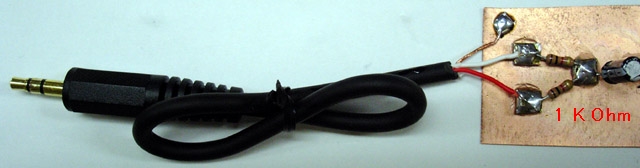
"The earlier model of iPod has an automatic shut-down system in it. When you pull out the plug of your headphone, it automatically stops working. When the left and right channels are short-circuited, the same thing happens. Presumably, you can use a stereo cable and solder the left (white) and right (red) lead together. Please use the left channel lead (white) only. Usually the left output is compatible with mono audio. If you, however, insist to mix the left and right output of your audio source into the transmitter, make a simple "interface" like this." Source: http://www.translocal.jp/radio/micro/howtosimplestTX.html
Radio Station Parts List
1 Resistor 820 Ohm
1 Resistor 4.7 K
1 Resistor 3.3K
1 Resistor 10K
1 Resistor 220K
1 Resistor 1K
1 Capacitor Ceramic Disc 10 pF
1 Capacitor Ceramic Disc .001 uF (102)
1 Capacitor Ceramic Disc .01 uF (103)
2 Capacitor Electrolytic 4.7 uF
1 Transistor 2SC1675 (or 2SC829) Q1
1 Transistor CS9013 Q2
1 Antenna Wire 16"
1 Coil (see text)
1 Electret Microphone
1 Printed Circuit Board
1 Enclosure
1 Printed Panel
Although controls are not necessary, adding a power switch and other capabilities may be desirable.
Spartan Version
On/Off Switch
A very spartan version with rudimentary controls is possible by using a rectangular project box with a hole for the mic protrusion and a hole for the on/off battery switch.
Basic Three Version
On/Off Switch
On the Air LED
Mute Switch
The on/off is a toggle switch wired to turn the 9 volt battery supply on or off.
The next upgrade can include a red LED for "on the air" monitor. This would wire in with the on/off switch and a dropping resistor to the LED.
Another handy feature is an audible mute switch. This would cut out the microphone and switch to a resistor with the same resistance as the microphone.
Deluxe Version
On/Off Switch
On the Air Red LED
Mic Mute
Variable Volume Control
External Sound Input
Signal Strength
Amplifier Monitor
Headset for Amp Monitor
External Power Supply
Switch from 3V, 6V, 9V (regulates output power)
2 Sound Source Mixer
External Antenna 1 or 2
Band - With different switchable "band" coils, it would be possible to change the transmitting frequency.
Trim - With a variable 0 to 20 pF capacitor, it would be possible to tune the transmitting frequency.
Clock - with added processor
Compass - with added processor
SOURCES
http://www.translocal.jp/radio/micro/howtosimplestTX.html
FM Radio Station Part 5 Index
http://humanoidolabs.blogspot.tw/2013/12/fm-radio-station-part-5-index.html