Showing posts with label fm. Show all posts

Tuesday, January 14, 2014

FM Radio Station QSL Card

FM RADIO STATION QSL CARD
Whisper Radio FM 102 releases the first version QSL reception card

Data given shows the location of the radio station as shown on a world map, the full output power of the transmitter in mWATTS, and the frequency of the radio station's transmitter in million of Hertz. The card contains the official seal of Humanoido Laboratories and the URL of the official blogspot.

A photo depicts the unique and historical first time setup when the radio station aired its first broadcast. The card is designed to confirm your FM radio reception for a given time, date, and program heard. Upon receipt of your email reception information, the E-CARD will be filled out with the appropriate data and emailed to you - the recipient. The email address to use is listed under "CONTACT" at the blogspot.

http://humanoidolabs.blogspot.tw/p/contact.html

To obtain the prestigious Whisper Radio Station's QSL card, listen to our broadcast noting the name of the program, time, and full date (day, month, year). Include your location, the strength of the signal on the 0-10 scale with 0 equal to no reception and 10 representing best reception. A QSL card cannot be given out without this information.

Other information is very useful. How stable is the signal, does it flutter, fade in and out, or remain steady? How long did you listen to the broadcast? Which receiver and antenna was used? You may apply for more than one QSL card with multiple dates and times of reception.

Whisper Radio's QSL cards are extremely valuable and rare, due to the part time intermittent nature of the programming and transmissions plus the limited range due to small output power and the diminutive antenna size.

It's best to consult our transmission guide when it becomes available (stay tuned to this blogger) and be ready to tune into a broadcast. Increasing the length of your radio's antenna will help and some radios will have greater sensitivity. This will increase the chances of hearing a broadcast and getting a QSL card.

Note, one cannot consult the blog and simply report the posting after the transmission. Our logs posted will detail the times of broadcast but not list the content. So to verify reception, listing the program's name or content will be important. To qualify, a report must fit the period of time after the broadcast and before the broadcast content posting at the blogger.

Each issued QSL card will contain the radio station's unique response. If you want a printed card, in addition to the E-Card, on a Mac computer, select Print and follow the setup. The card is full regulation postcard size at 4x6-inches. Printing on glossy stock heavy weight bond photo paper is recommended.

Monday, January 13, 2014

Brain Cortex Joins FM Radio Station

BRAIN CORTEX JOINS FM RADIO STATION
What do you get when crossing a machine brain cortex with an FM radio transmitter?

The project underway will adjust the brain cortex in a jar to speak English and then transmit the amplified audio speech via the radio station transmitter. As we know, the cortex is always talking so broadcasting its speech ideas is an interesting and useful idea, for not only monitoring its condition and health, but also to broadcast the state of its learning, retention and characteristics.

A serial brain cortex output of speech will be tailored to fit the speech center on the Parallax Propeller chip. This audio feed will interface to the FM Transmitter. The transmitter will be located inside the jar and switched on when transmitted speech is desired.

Tuesday, December 31, 2013

FM Radio Station Microphonic Part 25

FM RADIO STATION MICROPHONIC PART 25

HOW DO YOU TRANSMIT VOICE WITHOUT A MICROPHONE?

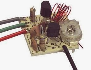
This is a two transistor circuit that makes up a wireless FM radio transmitter with a remarkable feature - it transmits voice without a microphone! 

It uses a floppy coil that moves upon receiving the vibrations from speech or other sources.


"This means it will vibrate when bumped and will even pick up sounds such as talking, music and footsteps and transmit audio just like a microphone.

Forget the phone lines as they are not needed for this example. Build the circuit and use 7 turns of thin wire on an 8-10mm pen and see how the coil picks up every sound in the room. Simply connect a 9v supply and the circuit starts broadcasting. The coil should be 6t and 3mm diameter, using 0.5mm enamelled wire."

Source
http://www.talkingelectronics.com/projects/Spy%20Circuits/SpyCircuits-3.html

FM Radio Station Notes Part 24

FM RADIO STATION NOTES PART 24

TUTORIAL: How Radio Waves are Produced
http://www.youtube.com/watch?v=aAcDM2ypBfE#t=186

FM TRANSMITTER
As a reference to going even smaller and more simple, this schematic shows possibly the most simple one transistor FM radio voice transmitter design, using a common 2N2222 transistor and only three capacitors and two resistors. There's only 7 electronic parts total to this assembly plus batteries and the antenna. A power on/off SPST switch should be added to the schematic.

Parts List
R1 Resistor 4.7K
R2 Resistor 220 ohms
C1 Capacitor .01uf
C2 Capacitor 33pf
C3 Capacitor 6.8pf
L1 Coil
Electret Microphone
2 - 1.5 Volt Battery

A slightly modified version is at this web site:
http://www.sentex.ca/~mec1995/circ/fmt2.htm
http://www.sentex.net/~mec1995/circ/circuits.htm

FM RECEIVER
The video also includes a schematic diagram for a very simple matching two stage FM radio receiver. This battery driven radio has only two transistors, amounting to 6 electronic parts plus batteries, switch and antenna.

Parts List
R1 Resistor 12K
C1 Capacitor 220n
T1, T2 Transistor BF199
C Variable Capacitor
3 Volt Battery
SPST Switch
Earphones
Antenna

BF199 transistor data sheet
http://pdf1.alldatasheet.com/datasheet-pdf/view/2947/MOTOROLA/BF199.html

MOST SIMPLE FM TRANSMITTER
The simple FM transmitter circuit shown above is a spinoff of this project. It uses only one resistor, one capacitor, one transistor and one coil. The article is found all over the web. It has no microphone but the coil is so microphonic that it will pick up noises in the room via vibrations on a table. The circuit does not have any section that actively tunes the frequency. The transistor turns on via the 47k resistor and this puts a pulse through the 15 turn winding. The magnetic flux from this winding passes through the 6 turn winding and into the base of the transistor via the 22n capacitor. This pulse is amplified by the transistor and the circuit is kept active. The frequency is determined by the 6 turn coil. By moving the turns together, the frequency will decrease.  The circuit transmits at 90MHz which is at the low end of the 88 to 108 MHz FM band. It has a very poor range and consumes 16mA.

http://www.circuitlab.org/2013/02/schematics-easy-build-rf-transmitter.html

http://skema-elektronik.blogspot.tw/2011_02_01_archive.html

http://circuit-diagram.hqew.net/Simplest-RF-Transmitter-circuit-diagram_4095.html

http://www.talkingelectronics.com/projects/Spy%20Circuits/SpyCircuits-1.html

This Google search link will find a lot more simple FM radio transmitter schematics and projects.


SIMPLEST FM TRANSMITTER
Here's another link to a project claiming also to be the simplest FM transmitter ever made.
http://circuitsdiy.com/the-simplest-f-m-transmitter-ever-made/

This circuit has audio input and needs only 2 resistors and 3 capacitors plus a coil and transistor.

"For input from low power output devices, such as mobile, computer’s sound card, the value of the unlabeled capacitor is 0.1 or 104. For higher wattage outputs, the value is 0.01 or 103. An optional microphone pre-amp can be also added in this circuit to enable it transmit voice directly."

ANTENNA
One idea to create the small transmitter antenna is to use a small wheel bicycle used spoke from a children's bike available from a bike shop probably for free.

How to Change a Dark Detector into an FM Transmitter
http://www.buildcircuit.com/fm-transmitter-and-dark-sensor/

A dark sensor can be converted to a simple FM transmitter using a similar schematic layout.

The dark sensor will light the LED as the output indicator. The transmitter substituted a microphone for the LDR.

FM TRANSMITTER
This FM transmitter is very sensitive and it has transmitting range of 30 meters with a 9-volt battery. Reducing battery power will reduce transmitter range.

Comments given at the link about the transmitter
The circuit may work but it relies on a “Q-factor” from the coil and capacitor in the tank circuit to produce a high voltage.

This high voltage gives the circuit a good range. Firstly the coil and capacitor should be near each other. The coil should not have long leads. and a 22n capacitor should be across the supply to give the circuit better performance. The value of C2 is too high. It should be 10p. The coil should be 5 turns. The electret mic should not be connected directly to the base of the transistor.

Monday, December 30, 2013

FM Radio Station Specs Part 23

FM RADIO STATION SPECS PART 23 
FM Radio Station statement of operating specifications, characteristics and purpose

Specifications 
Radio Type - Transmitter
Band - FM
Frequency Range - 88-108 MHz
Frequency Selection - tunable
Transmit power - under 100 mW
Range - desktop within room
Antenna - 1.75" diameter mini loop wire strand
Applications - hobby, school electronics, toy
Use - intermittent, testing, educational
Type - Personal Non-commercial
Power - 3 volts low power
Audio Source - voice electret microphone
Power source - battery
Typical Broadcast Duration- 30 seconds
Location - desktop
Size - pocket portable
Cost $4

Objectives 
* to fulfill the requirements of electronics design lab
* testing fm transmitter characteristics
* learning principles of broadcast radio stations

Applications 
* Transmit short range robot speech
* Classroom radio station project
* Electronics lab requirement
* Baby monitor
* Wireless pickup for guitar or ukelele
* Wireless microphone/KTV Singing
* Hobby or toy

Conclusion The micro FM radio station is a learning toy with short desktop range, a 1.75" antenna, and power under 100 milliwatts. No license is needed.

FM Radio Station Sensitivity Part 21

FM RADIO STATION SENSITIVITY CONTROL PART 21
Sensitivity circuit, adjust values as needed
This project installs a sensitivity control to the FM radio station. R1 is a static preset 1K ohm resistor as seen in the original schematic. Add an optional resistance with a 0 to 10K ohm variable potentiometer as shown. The variable potentiometer becomes the sensitivity control. Just dial in the amount required.

Calibrate the sensitivity control based on the sound source to improve the sensitivity and quality of the signal. The microphone will be the most sensitive when the value is at zero ohms. R1 is actually an optional resistor as shown. It's purpose is to limit the voice sensitivity, for example, a 10K resistor will resist the voice signal coming from microphone more as compared to the 1K resistor.

Sunday, December 29, 2013

FM Radio Station Housing Part 20

The idea is to put the radio station electronics into the smallest tiny enclosure possible and have remaining space for expansions. The yellow project box is perfect for this application, at 2 3/8" high x 1 1/8" deep x 4 1/8" long. One key feature, not shown here, is the front panel design label, that notates various controls and functions. Notations on the front will line up with actual controls at the top and the sides.
Cabinet, board, battery, antenna, controls

FM RADIO STATION TINY HOUSING PART 20
Perhaps the smallest radio station on the air today, tiny "Whisper Radio FM 102" is  housed in a miniature cabinet with space for expansion.

Whisper Radio -
"To hear a whisper you need to shut out the noise of the world…"


The radio station housing is an insulated rectangular yellow polymer cabinet. Components on the inside include the main board on the left with protruding microphone at top and antenna on the left, plus a 9VDC battery over on the right side.

At the top left is the mic, and at the top right is the on/off toggle switch and a red LED power-on monitor light. The best feature of mounting the microphone this way is the shortness of the leads which are kept at only one fourth inch long, thus minimizing interference. The push through microphone, without extending the leads, creates the highest quality, best signal, and minimizes distortion.

The cabinet is "drilled" with a soldering iron that easily melts holes into the plastic. Keep the internal board to the left, close enough to the side wall but keeping clearance mounting space to include the antenna jack.

The cabinet is large enough for installing many added features described in previous posts, like the mute switch, on-the-air monitor, tone control, etc. Refer to the controls post and the index link for more details.

FM Radio Station Controls Part 9
http://humanoidolabs.blogspot.tw/2013/12/fm-radio-station-controls.html


FM Radio Station Part 5 Index
http://humanoidolabs.blogspot.tw/2013/12/fm-radio-station-part-5-index.html 

FM Radio Station Broadcast Part 19

SciFi broadcast on Whisper Radio FM 102
FM RADIO STATION BROADCAST PART 19
Whisper Radio FM 102 broadcast a science fiction program, The Experiment - the Adventures of Tom Volt, on Monday December 30th 2013 at 12:30 to 12:48 am. A transcript of the program's text is found at the link below. This is from the famous Tom Volt adventure series authored by science fiction and science fact writer Humanoido.

The story goes on about the opening up of a quantum door into an alternate reality by a small group of scientist and describes their ultimate experiences.

The Adventures of Tom Volt - the Experiment
http://humanoidolabs.blogspot.tw/2013/04/the-experiment.html

FM Radio Station Schematic V1.1 Part 18

FM RADIO STATION SCHEMATIC V1.1 PART 18

The new updated v1.1 schematic for the FM radio station adds polarity notation to the electret microphone, corrects the size of notation for C3, and cleans up the antenna A1 symbol. It corrects the notation for transistors as Q1 and Q2 instead of T1 and T2, and introduces scaling.

A larger percent size schematic is provided for better clarity.

For more details about the FM Radio Station, refer to the index link.

FM Radio Station Part 5 Index
http://humanoidolabs.blogspot.tw/2013/12/fm-radio-station-part-5-index.html

FM Radio Station Electronics Part 17

FM RADIO STATION ELECTRONICS PART 17

This page assembles four important comparison electronic element views showing the FM Radio Station. The purpose is to check the components and their placements from the board to the schematic to confirm complete accuracy so the project can be duplicated.

At top left is the top side of the printed circuit board showing all components and their values.

At top right, the photo shows a back lit view with circuit traces.

At bottom left is the schematic diagram.

At bottom right is a photo of the bottom side, with photo reversal to match the top right back lit photo.

FM Radio Station Part 5 Index
http://humanoidolabs.blogspot.tw/2013/12/fm-radio-station-part-5-index.html

Friday, December 27, 2013

FM Radio Station Tone Part 16

FM RADIO STATION TONE CIRCUIT PART 16

Here's a modification to make a tone selector switch for the FM radio station's electret microphone output. Changes for actual use require adjusting the 8.2K ohm resistor and the 1nF capacitor based on the voltage supply.

A tone selector switch is used as a high pass filter to provide some tone adjustment. The 47nF setting reduces the low frequency and puts more of the midrange into useful talk power.

For FM, a 1uF setting is used which provides more full range audio suited to FM voice.

The electret mic element inherently has a strong gain. The intensity of voice and the position of person speaking can be adjusted to provide the best gain without distortion. Experiment with distances and component values to find the best results.

http://humanoidolabs.blogspot.tw/2013/12/fm-radio-station-controls.html

FM Radio Station Part 5 Index
http://humanoidolabs.blogspot.tw/2013/12/fm-radio-station-part-5-index.html

FM Radio Station Microphone Part 15

FM RADIO STATION MICROPHONE PART 15

Electret Microphone
http://sound.westhost.com/project93.htm

A typical electret microphone preamp circuit uses an FET in a common source configuration. The two-terminal electret capsule contains a FET which must be externally powered by supply voltage V+. The resistor sets the gain and output impedance. The audio signal appears at the output, after a DC-blocking capacitor.

THE MICROPHONE is an important part of the radio station. In a simplified circuit, it must deliver reasonable sound quality and provide a usable frequency response and audio level.


An electret condenser microphone (ECM) consists of a very light diaphragm (moving plate) and back plate (stationary or static plate) and has a permanent charge implanted in an electret material to provide polarizing voltage.

The principle of operation is that sound waves impinging on the diaphragm cause the capacitance between it and the back plate to change synchronously, this in turn induces an AC voltage on the back plate.

1. Foil Electret Condenser Microphone (also called Middle or Classic) - Type of condenser microphone where the electret material is the diaphragm. (Sometimes referred to as "Front" type.)

2. Back Electret Condenser Microphone -Type of condenser microphone where the electret material is the back plate.

3. Front Electret Condenser Microphone -Type of condenser microphone where the electret material is the inside of the case of the microphone.

"It must be realized that all electret mics (indeed, all mics) have one limitation we cannot readily change, and that is maximum SPL (Sound Pressure Level). Because electret capsules have an integral amplifier, there will always be a level where they will distort.

A capsule having a 10k feed resistor and supplied from a 15V supply will output well over 1V RMS quite easily, simply by having it close enough to your mouth as you speak loudly.

Even professional microphones (including dynamic types) are quite capable of 0dBm in close proximity to a floor tom or a loud singer. As a result, close vocal work, drums and brass instruments (trumpet, sax, etc) are capable of extremely high SPL, and are not really suitable candidates for electret mics. It is possible to get good performance at up to 115dB SPL quite easily - possibly more. 

Sensitivity
The sensitivity can be reduced, simply by reducing the value of the feed resistor. Again, there is a limit, as the internal FET amplifier can be driven into distortion regardless of what you do on the outside of the capsule. It is feasible to modify the capsule itself - but this is only possible with some models unless you are willing to make a few sacrifices (you can guarantee that you will ruin a couple in the process)." 

Frequency response
http://www.digikey.tw/Web%20Export/Supplier%20Content/PUI_668/PDF/PUI_ElectretCondenserMicrophone%20Basics.pdf?redirected=1
"Frequency response is the microphone's sensitivity performance in the frequency range of 0 to 20 kHz. Compared with the dynamic types, ECMs tend to have an extended response both at low and high frequencies, which is also smoother.In the case of dynamic types, the response limits are defined where the sensitivity has fallen by 3 dB relative to its value at 1 kHz. It is not stated in such terms for ECMs since they have a much wider frequency response." 

Usage
"To obtain the best results, avoid placing near reflective surfaces. If possible, mount in soft rubber to insulate from vibration. Treat ECMs as stat ic sensitive. Use specified heat sinking when soldering to ECMs. Use as little heat as possible for shortest time consistent with good joint. Avoid subjecting ECMs to high temperature and humidity that can degrade performance. The frequency response of ECMs may be too extended for communications application, in which case, it can be limited by suitable acoustic filtering in the intended housing or handset."

Microphone Setup
The legs on the electret microphone can extend through the cabinet. The mic is supported using a single strand color insulated copper wire. The mic electrical cable has a negative shield side to reduce interference. The microphone has a foam covering fabricated from a discarded headset. The wire support is bendable for best positioning.

Microphone Modifications
One improvement, since moving very close to the mic produces a much better signal and greater clarity, is a funnel that can direct the sound into the mic. This may be a great improvement and needs further testing. It may resemble a miniature old fashioned Thomas Edison "Gramophone." The cone can be fabricated from paper, cardboard or plastic from a bottle.

Microphone Measurement
The microphone resistance is measured at 1.37 ohms.

Microphone Impedance
http://www.edaboard.com/thread217554.html

http://www.gearslutz.com/board/geekslutz-forum/764918-what-should-follow-electret-mic-capsule.html 

Definitions
SPL - Sound Pressure Level

Microphone - Receiver that converts sound energy to electrical energy. Also described as a sound sensor.

Condenser - Another term used for a capacitor: two plates separated by a fixed distance capable of storing an electric charge.

Electret - An electrical property which describes the capability to retain electrical charges.

Pascal (Pa); bar (1Pa = 10 u bars) - Unit of pressure. For microphone applications, this unit refers to 
the pressure of sound on a microphone.

Links
http://humanoidolabs.blogspot.tw/2013/12/fm-radio-station-controls.html

http://en.wikipedia.org/wiki/Electret_microphone

FM Radio Station Part 5 Index
http://humanoidolabs.blogspot.tw/2013/12/fm-radio-station-part-5-index.html

FM Radio Station Mute Function Part 14

Radio Station mute function schematic
FM RADIO STATION MUTE FUNCTION PART 14

This circuit shows details for adding a mute function to the FM radio station. A switch will mute the microphone. When muted, the LED will stay lit.


Microphone Mute Function with LED monitor
When the DPDT switch is in a normalized position, the electret microphone is active, the LED is not connected, and broadcast takes place. When switched, the microphone cuts out, resistor R2 is connected to replace the microphone, and the LED lights. A carrier signal continues to broadcast but there is no sound. The LED is on a separate circuit and does not interfere with the microphone.
The microphone resistance is measured at 1.37 ohms (when not in the circuit).

Note: On the schematic, replace the text SPDT with DPDT.

http://humanoidolabs.blogspot.tw/2013/12/fm-radio-station-controls.html

FM Radio Station Part 5 Index
http://humanoidolabs.blogspot.tw/2013/12/fm-radio-station-part-5-index.html 

Wednesday, December 25, 2013

FM Radio Station Power Monitor Part 13

Radio switch schematic
FM RADIO STATION POWER MONITOR PART 13

Follow the schematic diagram to wire in a power switch and a red LED power-on monitor light.

Guide
The switch turns the radio radio station transmitter on and off. When on, the red LED will remain lit. The LED monitor light does not interfere with the radio station transmitter. This is the first modification add-on to the radio station.

Parts required, 1 LED, 1 resistor, 1 SPST or SPDT (for a future add on) toggle switch. Use the LED wiring guide pictorial and schematic to determine proper LED polarity.

Testing the LED power on/off indicator circuit. The resistor value of 820 ohms was determined with the use of a resistor ohm substitution box.
The guide shows a "looking down view" from above the LED. Shown in the schematic is a SPST switch. The actual radio transmitter will have a SPDT switch.

The 3mm red LED costs NT$1 each (US$.033 each) in a package of 100. The SPDT toggle switch SW1 is priced at NT$18 (US$.60). The resistor R1 is 820 ohm or the next larger resistance.

http://humanoidolabs.blogspot.tw/2013/12/fm-radio-station-controls.html

FM Radio Station Part 5 Index
http://humanoidolabs.blogspot.tw/2013/12/fm-radio-station-part-5-index.html 

FM Radio Station Power Part 12

FM RADIO STATION POWER PART 12

Online mW to W Converter
http://www.rapidtables.com/convert/power/mW_to_Watt.htm

The FM radio station at 100 mW is only .1 watt which is a mere whisper of more powerful radio stations. (1 Watt = 1000 mW)

Relative Power
Measuring the voltage at the antenna can determine the relative power measurement which is useful for tuning, i.e. to a minimal or maximum value. 

Measuring Power
http://www.zen22142.zen.co.uk/Circuits/Testgear/rfprobe.htm

http://preciserf.com/wp-content/uploads/2012/04/Appnote-4-Power-tests1.pdf 

From Code of Federal Regulations Telecommunications 47
Part 80 to End, FCC 80.259
"(c) A reserve transmitter must be equipped to measure antenna current. (d) The antenna power must be determined at the operating carrier frequency by the product of the antenna resistance and the square of the average antenna current both measured at the same point in the antenna circuit at approximately ground potential."

How to Measure Amps or Watts With a Multimeter
Measuring Amps

Step 1: Select the "Current" setting on the main dial of the multimeter. Choose a current range high enough for the circuit being tested. For example, if the circuit has a current that you estimate to be around five amps, select the "10 amp" setting instead of the "1 amp" option. Choosing a setting that is too low can overload the multimeter.

Step 2: Insert the leads into the multimeter connections labeled "current." Typically, the black lead should be connected to the "common" port, while the red lead is connected to a port that matches the selected current range. This arrangement varies, depending on the unit. Consult the multimeter labels carefully to confirm that the configuration is correct for measuring current.

Step 3: Place the multimeter leads into the circuit using a series configuration. The electricity must be redirected to flow completely through the multimeter to obtain an accurate reading. Current should usually move into the red lead and exit the black lead.

Step 4: Read the amount of amperage displayed on the multimeter. Remember to consider this number in the context of the selected current range. For example, the number "10.00" may indicate 10 amps on one setting but only 0.01 amps if the multimeter is set to the smaller "milliamps" range.

Measuring Watts
Step 1: Choose the "Voltage" setting on the multimeter dial. As you did when measuring the current, ensure that the appropriate voltage range is selected. It is usually a good idea to select the highest possible voltage range to prevent an overload.

Step 2: Configure the multimeter leads into the ports marked for "voltage." The black lead can usually remain in the "common" position. Move the red lead to the port labeled for the voltage range being tested.

Step 3: Connect the leads to the circuit in a parallel arrangement. The black lead should link to a negative or grounded point, while the red lead should be touched to a point of the circuit you wish to measure. Unlike a current measurement, a voltage test does not need to be completely redirected through the multimeter.

Step 4: Read the number on the multimeter display. As with current, remember to consider the context of the multimeter range setting.

Step 5: Multiply the amount of current and the amount of voltage in a circuit to determine the watts. For example, a motor circuit that uses 5 amps and 12 volts has 60 watts of power.


A SIMPLE POWER DETERMINATION
Use several incrementing known wattage light bulbs as a test to verify basic power operation of the transmitter. The lamp will present a load to the transmitter that's similar to an antenna. This test may provide a visual indication of the power output from the transmitter, and verify operation of the antenna coupler. Use grain of wheat bulbs for milliwatt ratings.

POWER FORMULA
P=EI, P=(I^2)R where E is voltage in volts and I is current in amps

ANTENNA
The antenna is a small circular loop with a 1.75-inch diameter. It's measurement of resistance for the tiny loop antenna is 0 ohms on every scale from 2K to 20M. The multi-strand antenna wire is a total of 6-inches long. This indicates that power output readings and measurements can be made at the antenna coupler with no antenna needed. The coupler is where the antenna attaches to the board.

The next step is to unravel a length of wire equal to a fundamental size of the wavelength and measure its resistance. If the value is still 0, increase the fundamental, from 1/32th wavelength to 1/16th, then repeat again if the wire still has zero resistance. At 1/8th, the antenna may be too long.

FM Radio Station Part 5 Index
http://humanoidolabs.blogspot.tw/2013/12/fm-radio-station-part-5-index.html

FM Radio Station Name Part 11

FM RADIO STATION NAME PART 11
Radio station naming conventions and ideas

Whisper Radio
To hear a whisper you need to shut out the noise of the world…

Similar terms: hush

FM Radio Station Part 5 Index
http://humanoidolabs.blogspot.tw/2013/12/fm-radio-station-part-5-index.html

FM Radio Station QSL Card Part 10

FM RADIO STATION QSL CARD PART 10
Ideas for the design of a radio station QSL card to confirm reception. The QSL card is a special card sent out to acknowledge the reception of a radio station.

* Country Map
* Radio Station Name
* Radio Station Logo
* Radio Station Transmitter Frequency
* Radio Station Transmitter Power
* Radio Station Photo, Equipment, Room, Antenna

* Blank - Name
* Blank - Time, day, month, year
* Blank - Signal strength
* Blank - General location of receiver
* Blank - Receiver Model

Tips for Printing a QSL Card
Use 110 pound or heavier paper for printing
The card should fit into an evelope

LINKS
Part 1
FM Radio Station Announcement
http://humanoidolabs.blogspot.tw/2013/12/big-brain-radio-station.html

Part 2
FM Radio Station Assembly

http://humanoidolabs.blogspot.tw/2013/12/radio-station-part-2.html

Part 3
FM Radio Station Assembly & Tips
http://humanoidolabs.blogspot.tw/2013/12/radio-station-part-3.html

Part 4
FM Radio Station Broadcasting Into Space

http://humanoidolabs.blogspot.tw/2013/12/radio-station-part-4.html

Part 5
FM Radio Station Index
http://humanoidolabs.blogspot.tw/2013/12/fm-radio-station-part-5-index.html

Part 6
FM Radio Station Programming
http://humanoidolabs.blogspot.tw/2013/12/fm-radio-station-programming-part-6.html
 

Part 7
FM Radio Station Testing
http://humanoidolabs.blogspot.tw/2013/12/fm-radio-station-testing-part-7.html

Part 8
FM Radio Station Broadcast Script
http://humanoidolabs.blogspot.tw/2013/12/fm-radio-station-broadcast-script-part-8.html

Part 9
FM Radio Station Controls 
http://humanoidolabs.blogspot.tw/2013/12/fm-radio-station-controls.html
 
Part 10
FM Radio Station QSL Card
http://humanoidolabs.blogspot.tw/2013/12/fm-radio-station-qsl-card-part-9.html 

FM Radio Station Controls Part 9

FM RADIO STATION CONTROLS PART 9
Over time, the simple FM Radio Station will have upgrades for more controls and more functionality. Below are numerous possible combinations.

Spartan "Basic Two" Radio Station 
On/Off Switch
Power On Red LED
http://humanoidolabs.blogspot.tw/2013/12/fm-radio-power-monitor-mod-part-13.html

A very spartan version with rudimentary controls is possible by using a rectangular project box with a hole for the mic protrusion and holes for the on/off battery switch and red LED.

Four Version Radio Station 
On/Off Switch
Power On Red LED
http://humanoidolabs.blogspot.tw/2013/12/fm-radio-power-monitor-mod-part-13.html

The on/off is a toggle switch wired to turn the 9 volt battery supply on or off. The LED wires in with the on/off switch and a dropping resistor to the LED to indicate when power is on.

Mute Switch
On the Air LED 
http://humanoidolabs.blogspot.tw/2013/12/fm-radio-station-mute-function-part-14.html

Another handy feature is an audible mute switch for the microphone. This cuts out the microphone and switches to a resistor with the same resistance as the microphone. The result is a transmitted broadcast carrier frequency without any sound from the microphone.

Deluxe Version Radio Station 
This deluxe radio station version has many more advanced controls bringing it closer to a professional radio station.

Switch On/Off
http://humanoidolabs.blogspot.tw/2013/12/fm-radio-power-monitor-mod-part-13.html
 
Switch External Antenna A or B
The external antenna switch requires two antenna banana jacks to plug in two antennas at the same time. The switch can enable antenna A or B.

Switch Power from 9V Battery to External Power Jack
A switch that powers off the 9 volt battery supply. Then, the banana power input jack can accept a lower voltage such 6 volts or 3 volts DC and/or simply run off an external power supply instead of internal batteries. This will affect the transmitters power and range. In some cases, it may be useful and necessary to reduce power and range to comply with local regulations.

Switch Mic Mute
http://humanoidolabs.blogspot.tw/2013/12/fm-radio-station-mute-function-part-14.html

Audible mute switch for the microphone. This cuts out the microphone and switches to a resistor with the same resistance as the microphone. The result is a transmitted broadcast carrier frequency without any sound from the microphone.

LED Power On/Off Red LED
http://humanoidolabs.blogspot.tw/2013/12/fm-radio-power-monitor-mod-part-13.html
 
LED On the Air White LED
http://humanoidolabs.blogspot.tw/2013/12/fm-radio-station-mute-function-part-14.html

Tone Selector
http://humanoidolabs.blogspot.tw/2013/12/fm-radio-station-tone-part-16.html
A tone selector switch is used as a high pass filter to provide some tone adjustment. The first setting at 47nF reduces the low frequency and puts more of the mid-range into useful talk power. For FM, the second setting uses a 1uF capacitor which provides more full range audio suited to FM voice.

Sensitivity Control
http://humanoidolabs.blogspot.tw/2013/12/fm-radio-sensitivity-part-21.html  

This modification replaces 1K resistor R1 with a 10K potentiometer to adjust the sensitivity of the microphone and the transmitter signal.

FM Radio Station Shielding
http://humanoidolabs.blogspot.tw/2013/12/fm-radio-station-shielding-part-22.html
The install of aluminum conductive ground shielding, inside the radio station housing, will minimize frequency shift and interference from outside sources such as a human hand.

Banana Jack External Power Supply Black (- ground)
Banana Jack External Power Supply Red (+ 9 volts max)
These are two banana jacks to plug in an external power supply
 
Banana Jack Ground (plug in for antenna load)
Banana Jack Antenna 
These are two banana jacks for two purposes. One, the plug in antenna and ground allows plugging in a light bulb load to determine power output and run tests. Two, an external antenna can plug in.

Banana Jack External Sound Input
This jack is for plugging in an audio source like an iPod, iPhone, or iPad. It can input a source of music or prerecorded programming for FM radio station broadcast.
 
Control Variable Volume
The variable volume control sets the volume of the input microphone. 

Amplifier Monitor Headset
This is an amplified sound monitor that feeds the mono broadcast sound to a headset for monitoring purposes. The amplifier is an LM386 chip. The circuit requires audio conversion. 

2 Sound Source Mixer
This is a basic two source sound mixer. It can mix one sound source with the microphone. It uses the External Sound Input and a control "mixing" knob.

Band - With different switchable or plug style "band" coils, it would be possible to make large changes to the transmitting frequency. It may be more feasible to interchange values of capacitors. With proper orientation, either the band coils or the capacitors could plug into the cabinet to enable particular transmit frequencies.

Trim - With a variable 0 to 20 pF capacitor connected in parallel with the coil, it would be possible to fine tune the transmitting frequency.

Clock - with added processor, a clock is an added feature useful for keeping programming on time

Compass - with added processor, a compass can verify the same equipment and antenna positioning, since position greatly effects transmission and signal characteristics

Program Timer - with added processor, a timer is useful for keeping programs on schedule

Program Timer Switch - with added processor, a timed switch can automate the start of radio programs

Signal Strength - the idea is to determine the strength of the signal being transmitted, using a common DVM and/or pickup coil to calibrate the transmitter to under 100 mW to comply with FCC Part 15 regulations in the USA. Also refer to the installment blog about determining power.
http://humanoidolabs.blogspot.tw/2013/12/radion.html

FM Radio Station Part 5 Index
http://humanoidolabs.blogspot.tw/2013/12/fm-radio-station-part-5-index.html