FM RADIO STATION QSL CARD
Whisper Radio FM 102 releases the first version QSL reception card
Data given shows the location of the radio station as shown on a world map, the full output power of the transmitter in mWATTS, and the frequency of the radio station's transmitter in million of Hertz. The card contains the official seal of Humanoido Laboratories and the URL of the official blogspot.
A photo depicts the unique and historical first time setup when the radio station aired its first broadcast. The card is designed to confirm your FM radio reception for a given time, date, and program heard. Upon receipt of your email reception information, the E-CARD will be filled out with the appropriate data and emailed to you - the recipient. The email address to use is listed under "CONTACT" at the blogspot.
http://humanoidolabs.blogspot.tw/p/contact.html
To obtain the prestigious Whisper Radio Station's QSL card, listen to our broadcast noting the name of the program, time, and full date (day, month, year). Include your location, the strength of the signal on the 0-10 scale with 0 equal to no reception and 10 representing best reception. A QSL card cannot be given out without this information.
Other information is very useful. How stable is the signal, does it flutter, fade in and out, or remain steady? How long did you listen to the broadcast? Which receiver and antenna was used? You may apply for more than one QSL card with multiple dates and times of reception.
Whisper Radio's QSL cards are extremely valuable and rare, due to the part time intermittent nature of the programming and transmissions plus the limited range due to small output power and the diminutive antenna size.
It's best to consult our transmission guide when it becomes available (stay tuned to this blogger) and be ready to tune into a broadcast. Increasing the length of your radio's antenna will help and some radios will have greater sensitivity. This will increase the chances of hearing a broadcast and getting a QSL card.
Note, one cannot consult the blog and simply report the posting after the transmission. Our logs posted will detail the times of broadcast but not list the content. So to verify reception, listing the program's name or content will be important. To qualify, a report must fit the period of time after the broadcast and before the broadcast content posting at the blogger.
Each issued QSL card will contain the radio station's unique response. If you want a printed card, in addition to the E-Card, on a Mac computer, select Print and follow the setup. The card is full regulation postcard size at 4x6-inches. Printing on glossy stock heavy weight bond photo paper is recommended.
BIG BRAIN made by Humanoido is a giant intelligent AI machine. Over twenty years in the making, living and sentient, approaching one trillion processors/constructs. Join us in the exciting adventure as it continues to evolve!
Showing posts with label frequency. Show all posts
Tuesday, January 14, 2014
Friday, December 27, 2013
FM Radio Station Tone Part 16
Here's a modification to make a tone selector switch for the FM radio station's electret microphone output. Changes for actual use require adjusting the 8.2K ohm resistor and the 1nF capacitor based on the voltage supply.
A tone selector switch is used as a high pass filter to provide some tone adjustment. The 47nF setting reduces the low frequency and puts more of the midrange into useful talk power.
For FM, a 1uF setting is used which provides more full range audio suited to FM voice.
The electret mic element inherently has a strong gain. The intensity of voice and the position of person speaking can be adjusted to provide the best gain without distortion. Experiment with distances and component values to find the best results.
http://humanoidolabs.blogspot.tw/2013/12/fm-radio-station-controls.html
FM Radio Station Part 5 Index
http://humanoidolabs.blogspot.tw/2013/12/fm-radio-station-part-5-index.html
Wednesday, December 25, 2013
FM Radio Station QSL Card Part 10
FM RADIO STATION QSL CARD PART 10
Ideas for the design of a radio station QSL card to confirm reception. The QSL card is a special card sent out to acknowledge the reception of a radio station.
* Country Map
* Radio Station Name
* Radio Station Logo
* Radio Station Transmitter Frequency
* Radio Station Transmitter Power
* Radio Station Photo, Equipment, Room, Antenna
* Blank - Name
* Blank - Time, day, month, year
* Blank - Signal strength
* Blank - General location of receiver
* Blank - Receiver Model
Tips for Printing a QSL Card
Use 110 pound or heavier paper for printing
The card should fit into an evelope
LINKS
Part 1
FM Radio Station Announcement
http://humanoidolabs.blogspot.tw/2013/12/big-brain-radio-station.html
Part 2
FM Radio Station Assembly
http://humanoidolabs.blogspot.tw/2013/12/radio-station-part-2.html
Part 3
FM Radio Station Assembly & Tips
http://humanoidolabs.blogspot.tw/2013/12/radio-station-part-3.html
Part 4
FM Radio Station Broadcasting Into Space
http://humanoidolabs.blogspot.tw/2013/12/radio-station-part-4.html
Part 5
FM Radio Station Index
http://humanoidolabs.blogspot.tw/2013/12/fm-radio-station-part-5-index.html
Part 6
FM Radio Station Programming
http://humanoidolabs.blogspot.tw/2013/12/fm-radio-station-programming-part-6.html
Part 7
FM Radio Station Testing
http://humanoidolabs.blogspot.tw/2013/12/fm-radio-station-testing-part-7.html
Part 8
FM Radio Station Broadcast Script
http://humanoidolabs.blogspot.tw/2013/12/fm-radio-station-broadcast-script-part-8.html
Part 9
FM Radio Station Controls
http://humanoidolabs.blogspot.tw/2013/12/fm-radio-station-controls.html
Part 10
FM Radio Station QSL Card
http://humanoidolabs.blogspot.tw/2013/12/fm-radio-station-qsl-card-part-9.html
Ideas for the design of a radio station QSL card to confirm reception. The QSL card is a special card sent out to acknowledge the reception of a radio station.
* Country Map
* Radio Station Name
* Radio Station Logo
* Radio Station Transmitter Frequency
* Radio Station Transmitter Power
* Radio Station Photo, Equipment, Room, Antenna
* Blank - Name
* Blank - Time, day, month, year
* Blank - Signal strength
* Blank - General location of receiver
* Blank - Receiver Model
Tips for Printing a QSL Card
Use 110 pound or heavier paper for printing
The card should fit into an evelope
LINKS
Part 1
FM Radio Station Announcement
http://humanoidolabs.blogspot.tw/2013/12/big-brain-radio-station.html
Part 2
FM Radio Station Assembly
http://humanoidolabs.blogspot.tw/2013/12/radio-station-part-2.html
Part 3
FM Radio Station Assembly & Tips
http://humanoidolabs.blogspot.tw/2013/12/radio-station-part-3.html
Part 4
FM Radio Station Broadcasting Into Space
http://humanoidolabs.blogspot.tw/2013/12/radio-station-part-4.html
Part 5
FM Radio Station Index
http://humanoidolabs.blogspot.tw/2013/12/fm-radio-station-part-5-index.html
Part 6
FM Radio Station Programming
http://humanoidolabs.blogspot.tw/2013/12/fm-radio-station-programming-part-6.html
Part 7
FM Radio Station Testing
http://humanoidolabs.blogspot.tw/2013/12/fm-radio-station-testing-part-7.html
Part 8
FM Radio Station Broadcast Script
http://humanoidolabs.blogspot.tw/2013/12/fm-radio-station-broadcast-script-part-8.html
Part 9
FM Radio Station Controls
http://humanoidolabs.blogspot.tw/2013/12/fm-radio-station-controls.html
Part 10
FM Radio Station QSL Card
http://humanoidolabs.blogspot.tw/2013/12/fm-radio-station-qsl-card-part-9.html
Monday, December 23, 2013
FM Radio Station Part 3 Assembly & Tips
HOW TO BUILD YOUR OWN FM RADIO STATION TRANSMITTER PART 3
PARTY TIME!!! Today is a solder party. Get out your guns (soldering guns) and prepare to melt some metal, putting metal (tin) on metal (copper).
Tuning the frequency
By a bit of trial and error plus observation with a nearby FM radio receiver, it is possible to tune the FM transmitter. Using the coil, either expand or compress the wire coils to change the frequency. A closer wire gap give a lower frequency and a loose wider spacing gap gives a higher frequency.
It is also possible to change the value of the ceramic capacitor which is in parallel with the coil. Some designs use a tunable variable capacitor to do the tuning. In this case, the variable capacitor would have a tunable range from 0 to 10 pF. Since this transmitter has no requirements for specific FM frequencies, the variable capacitor is not needed.
Experiment with the coil spacing first to determine the range. Keep the receiver at distance from the transmitter to minimize the reception of spurious radio signals. Make sure you've found the primary signal which will have the greatest signal strength.
The 10 pF capacitor is set to match the number of turns on the coil. With a greater capacitor value such as 20 or 50, the number of coil turns would be too much.
Antenna Length
First, here are some "getting started" approximate values already calculated for some frequencies. A full wave antenna for 98 Mhz, the center of the FM band, would be 119 inches. A half wave would be 59 inches. A quarter wave antenna for 98 Mhz would be 29 inches long. Try an eighth wave antenna at 14 inches long or a sixteenth wave antenna at 7 inches.
Online Whip Antenna Calculator
http://www.csgnetwork.com/antennagenericfreqlencalc.html
For more precise values, enter the frequency and the online program will calculate half and quarter wavelength whip antenna size. Requires browsers with enabled Javascript. "This calculator is designed to give the vertical length (height) of a particular whip type antenna, or the frequency of it. Enter one (only one) value, the desired frequency or the antenna length in any length field. Click on Calculate and the opposite value will be displayed in feet and inches or frequency in megahertz (Mhz). These are considered as generic calculations and you may wish to use them to learn general information about the antenna structure you are contemplating. Click on Clear Values to prepare for new calculations. Any antenna created with this calculator MUST be fine tuned for VSWR. None of the calculations are rounded or massaged and all calculated results are raw data."
Frequency Stability
The frequency may drift as the battery voltage becomes less. This is expected with this simple design. To offer more regulation, one could use a regulated power supply instead of the battery. The simple design presented here for exampling will use fresh batteries and some frequency drift will be expected. Do not use an AC adapter as these are generally not regulated and introduce interference.
Use with iPod, iPhone, iPad
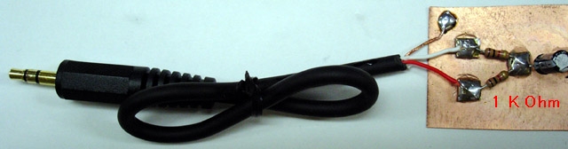
"The earlier model of iPod has an automatic shut-down system in it. When you pull out the plug of your headphone, it automatically stops working. When the left and right channels are short-circuited, the same thing happens. Presumably, you can use a stereo cable and solder the left (white) and right (red) lead together. Please use the left channel lead (white) only. Usually the left output is compatible with mono audio. If you, however, insist to mix the left and right output of your audio source into the transmitter, make a simple "interface" like this." Source: http://www.translocal.jp/radio/micro/howtosimplestTX.html
Radio Station Parts List
1 Resistor 820 Ohm
1 Resistor 4.7 K
1 Resistor 3.3K
1 Resistor 10K
1 Resistor 220K
1 Resistor 1K
1 Capacitor Ceramic Disc 10 pF
1 Capacitor Ceramic Disc .001 uF (102)
1 Capacitor Ceramic Disc .01 uF (103)
2 Capacitor Electrolytic 4.7 uF
1 Transistor 2SC1675 (or 2SC829) Q1
1 Transistor CS9013 Q2
1 Antenna Wire 16"
1 Coil (see text)
1 Electret Microphone
1 Printed Circuit Board
1 Enclosure
1 Printed Panel
Although controls are not necessary, adding a power switch and other capabilities may be desirable.
Spartan Version
On/Off Switch
A very spartan version with rudimentary controls is possible by using a rectangular project box with a hole for the mic protrusion and a hole for the on/off battery switch.
Basic Three Version
On/Off Switch
On the Air LED
Mute Switch
The on/off is a toggle switch wired to turn the 9 volt battery supply on or off.
The next upgrade can include a red LED for "on the air" monitor. This would wire in with the on/off switch and a dropping resistor to the LED.
Another handy feature is an audible mute switch. This would cut out the microphone and switch to a resistor with the same resistance as the microphone.
Deluxe Version
On/Off Switch
On the Air Red LED
Mic Mute
Variable Volume Control
External Sound Input
Signal Strength
Amplifier Monitor
Headset for Amp Monitor
External Power Supply
Switch from 3V, 6V, 9V (regulates output power)
2 Sound Source Mixer
External Antenna 1 or 2
Band - With different switchable "band" coils, it would be possible to change the transmitting frequency.
Trim - With a variable 0 to 20 pF capacitor, it would be possible to tune the transmitting frequency.
Clock - with added processor
Compass - with added processor
SOURCES
http://www.translocal.jp/radio/micro/howtosimplestTX.html
FM Radio Station Part 5 Index
http://humanoidolabs.blogspot.tw/2013/12/fm-radio-station-part-5-index.html
Sunday, December 22, 2013
FM Radio Station Part 2 Assembly
![]() |
| Flipped reverse side photo to match component side |
IN-HOUSE DIY RADIO STATION PART 2
![]() |
| Rotated left to right view for component placement |
Work is progressing on the electronic construction of the Lab's two stage exampling FM radio station. Stay tuned to this series of blogs as we supply the details of going on the air, as well as technical info so you can roll your own in-house radio station for fun.
The test transmitter printed circuit board has 17 components mounted and ready for soldering. This blog details the component placement and the circuit traces on the printed circuit board and includes transistor placement guides and a schematic for assembly. Note the two transistor identifications in the illustration showing keyed emitter, base and collector locations.
![]() |
| Verified leg identification ok |
Note that some countries and municipalities allow short range transmitters of this type and some do not. Be sure to first check local laws and regulations before proceeding with the project.
![]() |
| The copper printed circuit side of the board with through hole leads ready for hot soldering |
![]() |
| Ok to Use: MICRO Data/Japan data |
Frequency trimming is accomplished by stretching or compressing the coil or modifying the value of the ceramic parallel 10 pF capacitor.
Initially the frequency should be in the range of 88 to 108 mHz on the FM band.
![]() |
| Warning - do NOT use USHA India/LGE leg positions |
The cost of the first set of parts is NT$132 (US$4.42) and the backup duplicate parts are NT$120 (US$4.00). Thus far, combined cost is US$8.42 for the hardware.
The transistor leg identification does not agree from one data sheet to the next. See diagrams.
Careful with data sheets for the 2sc1675 transistor as there are discrepancies between the TO92 and TO92b case versions. For example, the equivalent Panasonic 2sc 829 equal to 2sc 1675 as a substitute is in agreement with the transistor placement of emitter, collector, base, therefore this is the arrangement to use.
FM Radio Station Part 5 Index
http://humanoidolabs.blogspot.tw/2013/12/fm-radio-station-part-5-index.html
Monday, August 26, 2013
Robot Explorer Log 5 Propeller Pins
DETERMINE FREE PROPELLER PINS
ROBOT EXPLORER LOG 5
CURRENT CHIP PINS FREE
PROPELLER 1: 11 PINS FREE
PROPELLER 2: 7 PINS FREE
We're taking this robot to the outer reaches of the Solar System! Follow along as we construct this little explorer craft that will go down to the surface of a new world that's alien to us.
In this update, we've removed the left and right IR navigation and replaced it with Ping ultrasonic navigation. The IR took up 4 pins so now the robot has 4 extra pins on the first propeller chip.
The ambient light level detectors are removed and replaced with the more sensitive TLS230R programmable chip.
On the second Propeller chip, two light to frequency converter chips (TLS230R) are added. Each chip uses 3 pins. Propeller two will have six more pins used.
On the second Propeller, the QTI sensor will be removed due to its limited range in the specs. This will free up 3 pins.
Also removed from the Propeller 2 are two CDS ambient light sensor cells freeing up two more pins.
The reason two light to frequency chips will be used is because one is pointed up to establish a baseline reference for calibration and the second chip will point down at the ground to help estimate the type of ground surface material, based on an average of light reflectivity.
Another reason for selecting the chip: the chip is much more sensitive compared to other sensors and it can be programmed for great sensitivity level or modified. This is a desired feature for exploring the outer planets and moons which have no more lighting than Earth's twilight.
The chip is also programmable to compensate for window dust and degradation, by increasing the light level sensitivity as needed.
Again, we attempted to combine both Propeller boards into one but there was a shortage of two pins.
ROBOT EXPLORER LOG 5
CURRENT CHIP PINS FREE
PROPELLER 1: 11 PINS FREE
PROPELLER 2: 7 PINS FREE
We're taking this robot to the outer reaches of the Solar System! Follow along as we construct this little explorer craft that will go down to the surface of a new world that's alien to us.
In this update, we've removed the left and right IR navigation and replaced it with Ping ultrasonic navigation. The IR took up 4 pins so now the robot has 4 extra pins on the first propeller chip.
The ambient light level detectors are removed and replaced with the more sensitive TLS230R programmable chip.
On the second Propeller chip, two light to frequency converter chips (TLS230R) are added. Each chip uses 3 pins. Propeller two will have six more pins used.
On the second Propeller, the QTI sensor will be removed due to its limited range in the specs. This will free up 3 pins.
Also removed from the Propeller 2 are two CDS ambient light sensor cells freeing up two more pins.
The reason two light to frequency chips will be used is because one is pointed up to establish a baseline reference for calibration and the second chip will point down at the ground to help estimate the type of ground surface material, based on an average of light reflectivity.
Another reason for selecting the chip: the chip is much more sensitive compared to other sensors and it can be programmed for great sensitivity level or modified. This is a desired feature for exploring the outer planets and moons which have no more lighting than Earth's twilight.
The chip is also programmable to compensate for window dust and degradation, by increasing the light level sensitivity as needed.
Again, we attempted to combine both Propeller boards into one but there was a shortage of two pins.
Subscribe to:
Posts (Atom)