FM RADIO STATION POWER PART 12
Online mW to W Converter
http://www.rapidtables.com/convert/power/mW_to_Watt.htm
The FM radio station at 100 mW is only .1 watt which is a mere whisper of more powerful radio stations. (1 Watt = 1000 mW)
Relative Power
Measuring
the voltage at the antenna can determine the relative power measurement
which is useful for tuning, i.e. to a minimal or maximum value.
Measuring Power
http://www.zen22142.zen.co.uk/Circuits/Testgear/rfprobe.htm
http://preciserf.com/wp-content/uploads/2012/04/Appnote-4-Power-tests1.pdf
From Code of Federal Regulations Telecommunications 47
Part 80 to End, FCC 80.259
"(c)
A reserve transmitter must be equipped to measure antenna current. (d)
The antenna power must be determined at the operating carrier frequency
by the product of the antenna resistance and the square of the average
antenna current both measured at the same point in the antenna circuit
at approximately ground potential."
How to Measure Amps or Watts With a Multimeter
Measuring Amps
Step
1: Select the "Current" setting on the main dial of the multimeter.
Choose a current range high enough for the circuit being tested. For
example, if the circuit has a current that you estimate to be around
five amps, select the "10 amp" setting instead of the "1 amp" option.
Choosing a setting that is too low can overload the multimeter.
Step
2: Insert the leads into the multimeter connections labeled "current."
Typically, the black lead should be connected to the "common" port,
while the red lead is connected to a port that matches the selected
current range. This arrangement varies, depending on the unit. Consult
the multimeter labels carefully to confirm that the configuration is
correct for measuring current.
Step 3: Place the multimeter
leads into the circuit using a series configuration. The electricity
must be redirected to flow completely through the multimeter to obtain
an accurate reading. Current should usually move into the red lead and
exit the black lead.
Step 4: Read the amount of amperage
displayed on the multimeter. Remember to consider this number in the
context of the selected current range. For example, the number "10.00"
may indicate 10 amps on one setting but only 0.01 amps if the multimeter
is set to the smaller "milliamps" range.
Measuring Watts
Step
1: Choose the "Voltage" setting on the multimeter dial. As you did when
measuring the current, ensure that the appropriate voltage range is
selected. It is usually a good idea to select the highest possible
voltage range to prevent an overload.
Step 2: Configure the
multimeter leads into the ports marked for "voltage." The black lead can
usually remain in the "common" position. Move the red lead to the port
labeled for the voltage range being tested.
Step 3: Connect the
leads to the circuit in a parallel arrangement. The black lead should
link to a negative or grounded point, while the red lead should be
touched to a point of the circuit you wish to measure. Unlike a current
measurement, a voltage test does not need to be completely redirected
through the multimeter.
Step 4: Read the number on the
multimeter display. As with current, remember to consider the context of
the multimeter range setting.
Step 5: Multiply the amount of
current and the amount of voltage in a circuit to determine the watts.
For example, a motor circuit that uses 5 amps and 12 volts has 60 watts
of power.
A SIMPLE POWER DETERMINATION
Use several incrementing known wattage light bulbs as a test to verify basic power operation of the
transmitter. The lamp will present a load to the
transmitter that's similar to an antenna. This
test may provide a visual indication of the power output from the
transmitter, and verify operation of the antenna coupler. Use grain of wheat bulbs for milliwatt ratings.
POWER FORMULA
P=EI, P=(I^2)R where E is voltage in volts and I is current in amps
ANTENNA
The antenna is a small circular loop with a 1.75-inch diameter. It's measurement of resistance for the tiny loop antenna is 0 ohms on every scale from 2K to 20M. The multi-strand antenna wire is a total of 6-inches long. This indicates that power output readings and measurements can be made at the antenna coupler with no antenna needed. The coupler is where the antenna attaches to the board.
The next step is to unravel a length of wire equal to a fundamental size of the wavelength and measure its resistance. If the value is still 0, increase the fundamental, from 1/32th wavelength to 1/16th, then repeat again if the wire still has zero resistance. At 1/8th, the antenna may be too long.
FM Radio Station Part 5 Index
http://humanoidolabs.blogspot.tw/2013/12/fm-radio-station-part-5-index.html
Showing posts with label antenna. Show all posts
Showing posts with label antenna. Show all posts
Wednesday, December 25, 2013
Tuesday, December 24, 2013
FM Radio Station Testing Part 7
 |
| The 9-volt powered mini radio station is set to broadcast on the FM band near 102 MHz with more tests using a tiny 1.75-inch circular loop antenna. Today's tests include a harmonic and range study, along with orientation reviews. A very sensitive Chinese multi band radio is at the receiving end. The photo does not show the actual test range distance. In this second day "on the air" test, a small script will be sent out over the "air waves." Stay tuned to this project and the radio station just keeps growing and growing. |
The next phase of the radio station is testing and calibration of the transmitter and equipment, and running more experiments to pace the radio station and see what works best.
* Range
* Transmitter Signature Footprint
* Detail & Extent of Harmonics
* Quality with Microphone
* Background Pickup Determination
* Orientation Positioning Effects
* Results of interchangeable Antenna
* Results with Different Antenna Designs
* Signature of Transmissions with Antenna Position
* Effects of Antenna Blockage
* Types of Material and the Effects on Wireless
* Results of Direct Audio Feed Bypassing Mic
* Results of Varied Lower Power Voltage
* Instrumentation Add On
* Mute Circuit Resistor Determination
* Power Determinations
FM Radio Station Part 5 Index
http://humanoidolabs.blogspot.tw/2013/12/fm-radio-station-part-5-index.html

Monday, December 23, 2013
FM Radio Station Part 3 Assembly & Tips
 |
| Fully assembled and ready for testing, the FM transmitter radio station is shown with a potential cabinet housing. Note how the microphone is repositioned top side for ease of positioning inside and through the yellow cabinet. |
HOW TO BUILD YOUR OWN FM RADIO STATION TRANSMITTER PART 3
PARTY TIME!!! Today is a solder party. Get out your guns (soldering guns) and prepare to melt some metal, putting metal (tin) on metal (copper).
Tuning the frequency
By a bit of trial and error plus observation with a nearby FM radio receiver, it is possible to tune the FM transmitter. Using the coil, either expand or compress the wire coils to change the frequency. A closer wire gap give a lower frequency and a loose wider spacing gap gives a higher frequency.
 |
| The completed solder side of the printed circuit board with a green loop antenna about 2.75-inches high and a microphone set outwards on one side to facilitate a good fit through the cabinet top. Prime use of this project is to fulfill the authors objective to own and operate a tiny radio station (at the toy level) - in this case, a tiny exampling FM band transmitter that can send broadcasting from one side of the table to the other side. Apps won't end there as the transmitter can have audio signal input into its stage, such as a Parallax Propeller chip's voice speech synthesizer signal inside the electric brain in a jar, and then transmit a speech signal through the jar, speaking wireless into a nearby radio. Building one transmitter is very cost effective at US$4. |
It is also possible to change the value of the ceramic capacitor which is in parallel with the coil. Some designs use a tunable variable capacitor to do the tuning. In this case, the variable capacitor would have a tunable range from 0 to 10 pF. Since this transmitter has no requirements for specific FM frequencies, the variable capacitor is not needed.
Experiment with the coil spacing first to determine the range. Keep the receiver at distance from the transmitter to minimize the reception of spurious radio signals. Make sure you've found the primary signal which will have the greatest signal strength.
 |
| Reference this image showing a different orientation for clarity, to the photo in post part number 2 for circuit path positions. Note the coil spacing to change the frequency to a "quiet spot" on the upper FM dial. |
Antenna Length
First, here are some "getting started" approximate values already calculated for some frequencies. A full wave antenna for 98 Mhz, the center of the FM band, would be 119 inches. A half wave would be 59 inches. A quarter wave antenna for 98 Mhz would be 29 inches long. Try an eighth wave antenna at 14 inches long or a sixteenth wave antenna at 7 inches.
Online Whip Antenna Calculator
http://www.csgnetwork.com/antennagenericfreqlencalc.html
For more precise values, enter the frequency and the online program will calculate half and quarter wavelength whip antenna size. Requires browsers with enabled Javascript. "This calculator is designed to give the vertical length (height) of a particular whip type antenna, or the frequency of it. Enter one (only one) value, the desired frequency or the antenna length in any length field. Click on Calculate and the opposite value will be displayed in feet and inches or frequency in megahertz (Mhz). These are considered as generic calculations and you may wish to use them to learn general information about the antenna structure you are contemplating. Click on Clear Values to prepare for new calculations. Any antenna created with this calculator MUST be fine tuned for VSWR. None of the calculations are rounded or massaged and all calculated results are raw data."
Frequency Stability
The frequency may drift as the battery voltage becomes less. This is expected with this simple design. To offer more regulation, one could use a regulated power supply instead of the battery. The simple design presented here for exampling will use fresh batteries and some frequency drift will be expected. Do not use an AC adapter as these are generally not regulated and introduce interference.
Use with iPod, iPhone, iPad
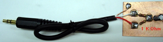
"The earlier model of iPod has an automatic shut-down system in it. When you pull out the plug of your headphone, it automatically stops working. When the left and right channels are short-circuited, the same thing happens. Presumably, you can use a stereo cable and solder the left (white) and right (red) lead together. Please use the left channel lead (white) only. Usually the left output is compatible with mono audio. If you, however, insist to mix the left and right output of your audio source into the transmitter, make a simple "interface" like this." Source: http://www.translocal.jp/radio/micro/howtosimplestTX.html
Radio Station Parts List
1 Resistor 820 Ohm
1 Resistor 4.7 K
1 Resistor 3.3K
1 Resistor 10K
1 Resistor 220K
1 Resistor 1K
1 Capacitor Ceramic Disc 10 pF
1 Capacitor Ceramic Disc .001 uF (102)
1 Capacitor Ceramic Disc .01 uF (103)
2 Capacitor Electrolytic 4.7 uF
1 Transistor 2SC1675 (or 2SC829) Q1
1 Transistor CS9013 Q2
1 Antenna Wire 16"
1 Coil (see text)
1 Electret Microphone
1 Printed Circuit Board
1 Enclosure
1 Printed Panel
Although controls are not necessary, adding a power switch and other capabilities may be desirable.
Spartan Version
On/Off Switch
A very spartan version with rudimentary controls is possible by using a rectangular project box with a hole for the mic protrusion and a hole for the on/off battery switch.
Basic Three Version
On/Off Switch
On the Air LED
Mute Switch
The on/off is a toggle switch wired to turn the 9 volt battery supply on or off.
The next upgrade can include a red LED for "on the air" monitor. This would wire in with the on/off switch and a dropping resistor to the LED.
Another handy feature is an audible mute switch. This would cut out the microphone and switch to a resistor with the same resistance as the microphone.
Deluxe Version
On/Off Switch
On the Air Red LED
Mic Mute
Variable Volume Control
External Sound Input
Signal Strength
Amplifier Monitor
Headset for Amp Monitor
External Power Supply
Switch from 3V, 6V, 9V (regulates output power)
2 Sound Source Mixer
External Antenna 1 or 2
Band - With different switchable "band" coils, it would be possible to change the transmitting frequency.
Trim - With a variable 0 to 20 pF capacitor, it would be possible to tune the transmitting frequency.
Clock - with added processor
Compass - with added processor
SOURCES
http://www.translocal.jp/radio/micro/howtosimplestTX.html
FM Radio Station Part 5 Index
http://humanoidolabs.blogspot.tw/2013/12/fm-radio-station-part-5-index.html
Sunday, December 22, 2013
FM Radio Station Part 2 Assembly
 |
| Flipped reverse side photo to match component side |
   |
| MINI FM RADIO STATION Note top side component placement. Top two holes are for the 9-volt battery clip leads with ground on the left side. The left bottom hole and the bottom right hole are for the antenna connection. |
 |
| Connections are easily seen when the printed circuit board is back lit, showing the circuit board traces on the reverse side. This makes it easier to match component locations to the schematic diagram. |
 |
| Schematic diagram for a two stage transistor FM transmitter. Features microphone driven audio input, with tunable frequency range with L1. Operates on a 9-volt battery. Range tests are yet to be determined but the frequency appears to be around 100MHz on the FM band. |
IN-HOUSE DIY RADIO STATION PART 2
 |
| Rotated left to right view for component placement |
Work is progressing on the electronic construction of the Lab's two stage exampling FM radio station. Stay tuned to this series of blogs as we supply the details of going on the air, as well as technical info so you can roll your own in-house radio station for fun.
The test transmitter printed circuit board has 17 components mounted and ready for soldering. This blog details the component placement and the circuit traces on the printed circuit board and includes transistor placement guides and a schematic for assembly. Note the two transistor identifications in the illustration showing keyed emitter, base and collector locations.
 |
| Verified leg identification ok |
Note that some countries and municipalities allow short range transmitters of this type and some do not. Be sure to first check local laws and regulations before proceeding with the project.
 |
| The copper printed circuit side of the board with through hole leads ready for hot soldering |
 |
| Ok to Use: MICRO Data/Japan data |
Frequency trimming is accomplished by stretching or compressing the coil or modifying the value of the ceramic parallel 10 pF capacitor.
Initially the frequency should be in the range of 88 to 108 mHz on the FM band.
 |
| Warning - do NOT use USHA India/LGE leg positions |
The cost of the first set of parts is NT$132 (US$4.42) and the backup duplicate parts are NT$120 (US$4.00). Thus far, combined cost is US$8.42 for the hardware.
The transistor leg identification does not agree from one data sheet to the next. See diagrams.
Careful with data sheets for the 2sc1675 transistor as there are discrepancies between the TO92 and TO92b case versions. For example, the equivalent Panasonic 2sc 829 equal to 2sc 1675 as a substitute is in agreement with the transistor placement of emitter, collector, base, therefore this is the arrangement to use.
FM Radio Station Part 5 Index
http://humanoidolabs.blogspot.tw/2013/12/fm-radio-station-part-5-index.html
Sunday, July 7, 2013
Radio Telescope Radar Tracking
PART 4 - Tracking Radar Objects in Space
RADIO TELESCOPE RADAR TRACKING
This blog describes more add on capability for the radio telescope which we recently put into operation. This uses the same equipment to track objects in space which reflect radar waves.
The radar transmitter puts out waves that originate from Earth as man-made transmitters owned by the Air Force and NASA, used to track the positions of space objects. The FM radio band will work as a receiver, more specifically try the VHF-UHF tuning bands. The radio's monopole antenna is acceptable and try repositioning it for best reception. The antenna with receiver works well on an alt-azimuth mount with a flex wire to feed the audio to the computer processors sound card for signal processing.
This link offers more information.
http://www.neatinformation.com/science/space%20radar.html
RADIO TELESCOPE RADAR TRACKING
This blog describes more add on capability for the radio telescope which we recently put into operation. This uses the same equipment to track objects in space which reflect radar waves.
The radar transmitter puts out waves that originate from Earth as man-made transmitters owned by the Air Force and NASA, used to track the positions of space objects. The FM radio band will work as a receiver, more specifically try the VHF-UHF tuning bands. The radio's monopole antenna is acceptable and try repositioning it for best reception. The antenna with receiver works well on an alt-azimuth mount with a flex wire to feed the audio to the computer processors sound card for signal processing.
This link offers more information.
http://www.neatinformation.com/science/space%20radar.html
Tuesday, July 2, 2013
Radio Telescope Observatory Lab 58

LOOKING FOR ET
A radio telescope laboratory is in the works at the Asian Arena International Taiwan location, being built as part of the open sky-faced balcony radio observatory BRO project. The purpose of the radio telescope is to observe radio sources, particularly the Sun and the planet Jupiter, as well as any signals that may be of extraterrestrial origin.
LOCATION
Taiwan is an island favorably faced by ocean on all sides - the South China Sea, the East China sea, and the Pacific Ocean. This water is uninhabited and creates a surrounding zone of quiet radio, more than a land surrounded counterpart. Taiwan has the greatest zones of uninhabited ocean space to the North towards Japan and to the east leading out into the deep ocean. Ideally situated is the city of Taipei to the extreme North of Taiwan that takes advantages of these oceanic voids.
EQUIPMENT
The equipment deploys a decametric 10-band radio receiver and a custom constructed antenna designed to match the correct frequency or to engage in a tunable sweep. Additional components include an electronic computerized strip chart recorder which handles the signals fed through the computer's sound card, and a DVM for numerical output, plus an audio buffer to match the signals to the equipment. Additionally, audio out permits one to listen to the actual signal for tuning and signal acquisition. This also helps in the case of guiding on moveable objects like satellites, spy planes, military vehicles, and alien spacecraft should one make a dramatic entrance into air space.
ANTENNA
It's planned the antenna will have a moveable scaled mounting to be able to track both natural and artificial sources, including satellites and aircraft. As part of a Tiny SETI Program, the mount will move to track anomalous sources which could be of extraterrestrial origin.
FIRST CONTACT FREQUENCY
We don't necessarily subscribe to the notion that first contact will result in the microwave spectrum. We believe other broadband frequencies may be used for wide spectrum first contact. Our deepest belief is that advanced aliens would use a technology for transmitting and receiving particles which we are currently not aware of.
DETECTING ALIEN CIVILIZATIONS
This radio observatory could tap into an alien civilization which is evolving around a star, given its radio signature is bright enough to be seen by the equipment. So this technique of First Contact uses this method which first detects their TV, radio, and other sources of activity. This is a viable program that could examine closer star systems in the North from East to West in scans, as recently planets around stars were discovered as close as a hundred light years away that reside in the habitat zone where it is believed that life could be supported.
THE APPEARANCE OF ALIENS
Most of these detected planets are quite large, having their detection based on the gravity wobble influencing its star. The intense gravity on these planets would evolve very large life which is able to cope with great gravity. Our technique is indicative of detecting radio bright planets and not directly observing the stars. So these planets detected could be very small but exhibiting very bright radio signatures.
PHONE HOME
In this setup, it's ET who needs to phone us as we have the receiver. We are not going to transmit any signals or give out our location position indicating that any intelligent edible life may live on Earth. The problem is that predator ET may live out there and want to eat us. The Asian Arena International Taiwan Radio Open Sky-faced Balcony Observatory Laboratory 58 is ideal to mask our identity with only one way communications from the aliens to the Earth.
BUDGET
So far, the project has spent a total of about $10 for the multi-band tunable receiver. The antenna is in the works. The software is Mac based and free. The computer is the Big Brain already in operation. The buffer will be constructed. The DVM is already in the lab. Additional software may be provided by the BIG Brain using Propeller chip technology. It's possible other software will be programmed and written on a supporting iMac computer. Our budget, not counting the equipment already on hand, is under $50. A target goal would be $25. Operating budget would ideally run at about $5 a month for supplies and materials.
R&D
The Asian Arena International Taiwan Radio Open Sky-faced Balcony Observatory Laboratory 58 will be heavy into Research and Development, and the collection & analysis of observational data.
Subscribe to:
Posts (Atom)