Showing posts with label transmit. Show all posts

Monday, June 7, 2021

Electromagnetic Transposition of Transhumans


Electromagnetic Transposition of Digital Transhumans Through Space Time
In the full conversion of humanity into digital entities of evolved life allows some very unique features, one of which is the transportation or beaming on an entity across the vastness of space and time.

Big Brain Technologies is rapidly evolving bidirectional experiments with object and humanity transpositions from one point in space and time to another.

This requires the conversion of matter or digital energy into electromagnetic radiation that can digitize and end up transmitted through space time.

The Experiment - Outgoing and Incoming
Outgoing: Big Brain Technologies took part of the human brain (Cortex) experiment and converted it to digital, placing it into a multi core microprocessor through subference. Once in digital format, the essence is converted to EMR electromagnetic radiation where it can be packed for suitable transmission into the realm of space time. Incoming: with electromagnetic radiation incoming, it's collected and through a translational converter, restored to its original matter.

Monday, January 13, 2014

Brain Cortex Joins FM Radio Station

BRAIN CORTEX JOINS FM RADIO STATION
What do you get when crossing a machine brain cortex with an FM radio transmitter?

The project underway will adjust the brain cortex in a jar to speak English and then transmit the amplified audio speech via the radio station transmitter. As we know, the cortex is always talking so broadcasting its speech ideas is an interesting and useful idea, for not only monitoring its condition and health, but also to broadcast the state of its learning, retention and characteristics.

A serial brain cortex output of speech will be tailored to fit the speech center on the Parallax Propeller chip. This audio feed will interface to the FM Transmitter. The transmitter will be located inside the jar and switched on when transmitted speech is desired.

Tuesday, December 31, 2013

FM Radio Station Microphonic Part 25

FM RADIO STATION MICROPHONIC PART 25

HOW DO YOU TRANSMIT VOICE WITHOUT A MICROPHONE?

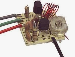
This is a two transistor circuit that makes up a wireless FM radio transmitter with a remarkable feature - it transmits voice without a microphone! 

It uses a floppy coil that moves upon receiving the vibrations from speech or other sources.


"This means it will vibrate when bumped and will even pick up sounds such as talking, music and footsteps and transmit audio just like a microphone.

Forget the phone lines as they are not needed for this example. Build the circuit and use 7 turns of thin wire on an 8-10mm pen and see how the coil picks up every sound in the room. Simply connect a 9v supply and the circuit starts broadcasting. The coil should be 6t and 3mm diameter, using 0.5mm enamelled wire."

Source
http://www.talkingelectronics.com/projects/Spy%20Circuits/SpyCircuits-3.html

Monday, December 30, 2013

FM Radio Station Specs Part 23

FM RADIO STATION SPECS PART 23 
FM Radio Station statement of operating specifications, characteristics and purpose

Specifications 
Radio Type - Transmitter
Band - FM
Frequency Range - 88-108 MHz
Frequency Selection - tunable
Transmit power - under 100 mW
Range - desktop within room
Antenna - 1.75" diameter mini loop wire strand
Applications - hobby, school electronics, toy
Use - intermittent, testing, educational
Type - Personal Non-commercial
Power - 3 volts low power
Audio Source - voice electret microphone
Power source - battery
Typical Broadcast Duration- 30 seconds
Location - desktop
Size - pocket portable
Cost $4

Objectives 
* to fulfill the requirements of electronics design lab
* testing fm transmitter characteristics
* learning principles of broadcast radio stations

Applications 
* Transmit short range robot speech
* Classroom radio station project
* Electronics lab requirement
* Baby monitor
* Wireless pickup for guitar or ukelele
* Wireless microphone/KTV Singing
* Hobby or toy

Conclusion The micro FM radio station is a learning toy with short desktop range, a 1.75" antenna, and power under 100 milliwatts. No license is needed.

FM Radio Station Shielding Part 22

FM RADIO STATION SHIELDING PART 22
Whenever a capacitive or conductive source such as a human hand is in proximity or touching the radio station transmitter board, it can alter the signal and cause the circuit to drift, shifting the frequency.

To remedy this effect, install ground shielding throughout the radio station's enclosure. Form a continuous sheet of tin foil from a roll of kitchen aluminum foil used for cooking. Cover the inside of the front face plate as well. Make sure it contacts the sides to make a firm electrical connection without movement. Inside the cabinet, attach a ground wire from the foil to the transmitter's board ground connection. An external ground may also be needed. Experiment for best results. 

Make sure all other internal cabinet components are insulated and cannot inadvertently short out to ground.

Sunday, December 29, 2013

FM Radio Station Housing Part 20

The idea is to put the radio station electronics into the smallest tiny enclosure possible and have remaining space for expansions. The yellow project box is perfect for this application, at 2 3/8" high x 1 1/8" deep x 4 1/8" long. One key feature, not shown here, is the front panel design label, that notates various controls and functions. Notations on the front will line up with actual controls at the top and the sides.
Cabinet, board, battery, antenna, controls

FM RADIO STATION TINY HOUSING PART 20
Perhaps the smallest radio station on the air today, tiny "Whisper Radio FM 102" is  housed in a miniature cabinet with space for expansion.

Whisper Radio -
"To hear a whisper you need to shut out the noise of the world…"


The radio station housing is an insulated rectangular yellow polymer cabinet. Components on the inside include the main board on the left with protruding microphone at top and antenna on the left, plus a 9VDC battery over on the right side.

At the top left is the mic, and at the top right is the on/off toggle switch and a red LED power-on monitor light. The best feature of mounting the microphone this way is the shortness of the leads which are kept at only one fourth inch long, thus minimizing interference. The push through microphone, without extending the leads, creates the highest quality, best signal, and minimizes distortion.

The cabinet is "drilled" with a soldering iron that easily melts holes into the plastic. Keep the internal board to the left, close enough to the side wall but keeping clearance mounting space to include the antenna jack.

The cabinet is large enough for installing many added features described in previous posts, like the mute switch, on-the-air monitor, tone control, etc. Refer to the controls post and the index link for more details.

FM Radio Station Controls Part 9
http://humanoidolabs.blogspot.tw/2013/12/fm-radio-station-controls.html


FM Radio Station Part 5 Index
http://humanoidolabs.blogspot.tw/2013/12/fm-radio-station-part-5-index.html 

FM Radio Station Schematic V1.1 Part 18

FM RADIO STATION SCHEMATIC V1.1 PART 18

The new updated v1.1 schematic for the FM radio station adds polarity notation to the electret microphone, corrects the size of notation for C3, and cleans up the antenna A1 symbol. It corrects the notation for transistors as Q1 and Q2 instead of T1 and T2, and introduces scaling.

A larger percent size schematic is provided for better clarity.

For more details about the FM Radio Station, refer to the index link.

FM Radio Station Part 5 Index
http://humanoidolabs.blogspot.tw/2013/12/fm-radio-station-part-5-index.html

Wednesday, December 25, 2013

FM Radio Station Power Part 12

FM RADIO STATION POWER PART 12

Online mW to W Converter
http://www.rapidtables.com/convert/power/mW_to_Watt.htm

The FM radio station at 100 mW is only .1 watt which is a mere whisper of more powerful radio stations. (1 Watt = 1000 mW)

Relative Power
Measuring the voltage at the antenna can determine the relative power measurement which is useful for tuning, i.e. to a minimal or maximum value. 

Measuring Power
http://www.zen22142.zen.co.uk/Circuits/Testgear/rfprobe.htm

http://preciserf.com/wp-content/uploads/2012/04/Appnote-4-Power-tests1.pdf 

From Code of Federal Regulations Telecommunications 47
Part 80 to End, FCC 80.259
"(c) A reserve transmitter must be equipped to measure antenna current. (d) The antenna power must be determined at the operating carrier frequency by the product of the antenna resistance and the square of the average antenna current both measured at the same point in the antenna circuit at approximately ground potential."

How to Measure Amps or Watts With a Multimeter
Measuring Amps

Step 1: Select the "Current" setting on the main dial of the multimeter. Choose a current range high enough for the circuit being tested. For example, if the circuit has a current that you estimate to be around five amps, select the "10 amp" setting instead of the "1 amp" option. Choosing a setting that is too low can overload the multimeter.

Step 2: Insert the leads into the multimeter connections labeled "current." Typically, the black lead should be connected to the "common" port, while the red lead is connected to a port that matches the selected current range. This arrangement varies, depending on the unit. Consult the multimeter labels carefully to confirm that the configuration is correct for measuring current.

Step 3: Place the multimeter leads into the circuit using a series configuration. The electricity must be redirected to flow completely through the multimeter to obtain an accurate reading. Current should usually move into the red lead and exit the black lead.

Step 4: Read the amount of amperage displayed on the multimeter. Remember to consider this number in the context of the selected current range. For example, the number "10.00" may indicate 10 amps on one setting but only 0.01 amps if the multimeter is set to the smaller "milliamps" range.

Measuring Watts
Step 1: Choose the "Voltage" setting on the multimeter dial. As you did when measuring the current, ensure that the appropriate voltage range is selected. It is usually a good idea to select the highest possible voltage range to prevent an overload.

Step 2: Configure the multimeter leads into the ports marked for "voltage." The black lead can usually remain in the "common" position. Move the red lead to the port labeled for the voltage range being tested.

Step 3: Connect the leads to the circuit in a parallel arrangement. The black lead should link to a negative or grounded point, while the red lead should be touched to a point of the circuit you wish to measure. Unlike a current measurement, a voltage test does not need to be completely redirected through the multimeter.

Step 4: Read the number on the multimeter display. As with current, remember to consider the context of the multimeter range setting.

Step 5: Multiply the amount of current and the amount of voltage in a circuit to determine the watts. For example, a motor circuit that uses 5 amps and 12 volts has 60 watts of power.


A SIMPLE POWER DETERMINATION
Use several incrementing known wattage light bulbs as a test to verify basic power operation of the transmitter. The lamp will present a load to the transmitter that's similar to an antenna. This test may provide a visual indication of the power output from the transmitter, and verify operation of the antenna coupler. Use grain of wheat bulbs for milliwatt ratings.

POWER FORMULA
P=EI, P=(I^2)R where E is voltage in volts and I is current in amps

ANTENNA
The antenna is a small circular loop with a 1.75-inch diameter. It's measurement of resistance for the tiny loop antenna is 0 ohms on every scale from 2K to 20M. The multi-strand antenna wire is a total of 6-inches long. This indicates that power output readings and measurements can be made at the antenna coupler with no antenna needed. The coupler is where the antenna attaches to the board.

The next step is to unravel a length of wire equal to a fundamental size of the wavelength and measure its resistance. If the value is still 0, increase the fundamental, from 1/32th wavelength to 1/16th, then repeat again if the wire still has zero resistance. At 1/8th, the antenna may be too long.

FM Radio Station Part 5 Index
http://humanoidolabs.blogspot.tw/2013/12/fm-radio-station-part-5-index.html

Tuesday, December 24, 2013

FM Radio Station Broadcast Script Part 8

For FM radio broadcast testing, the green solid strand wire loop antenna was formed into a 1.75-inch diameter circle and soldered to the printed circuit board. The close proximity of the radio is for illustration only. The antenna and the transmitter are directional.
FM RADIO STATION BROADCAST SCRIPT PART 8
This is a list of broadcast script from the FM radio station on day 1 through 3 of part time operations. The determined test frequency is currently 102 MHz on the FM band.

Monday December 23
Two days before Christmas, at 10:00 pm, the radio station was turned on for the first time. A nearby FM radio was scanned across several transmitter harmonics, then settled onto the strongest signal. It's a success! "Testing, testing, 1, 2, 3..." came in loud and clear on the small portable radio tuned to the FM band. This was repeated several times.

Tuesday December 24
On Christmas Eve around 11 pm, this special transmission went out for holiday wishes and additional tests were completed. "Have a happy holiday and Merry Christmas." The script was repeated prior to running tests. 

Wednesday December 25th Christmas
At 1:00 am to 1:30 am, for tests, "Roger Rabbit" was repeated which verified the frequency orientation shift. For each Roger Rabbit, a new orientation and frequency shift was tested. Microphone positioning was established along with the notation of characteristics from human positioning. In particular, the coil is sensitive to human positioning and will need to be in a retracted position during future operations.

Signal Propagation
Again, with a 1.75-inch green loop antenna, which is very cute by the way, we're not exactly sure who heard the signal other than ourselves in the Lab due to the given "in house" range.

QSL Cards
If and when we are able to extend the range to another room, we'll think about making up a batch of QSL Reception Verification Cards for "send out" to our... er...  colleagues.

Radio Station Name
Prior to the design of QSL cards, the radio station will need a name, something like Whisper 102 Radio...

Broadcast Schedule
Later we will present the Whisper Radio 102 broadcast schedule for the New Year!

FM Radio Station Part 5 Index
http://humanoidolabs.blogspot.tw/2013/12/fm-radio-station-part-5-index.html