Showing posts with label mic. Show all posts

Tuesday, December 31, 2013

FM Radio Station Microphonic Part 25

FM RADIO STATION MICROPHONIC PART 25

HOW DO YOU TRANSMIT VOICE WITHOUT A MICROPHONE?

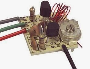
This is a two transistor circuit that makes up a wireless FM radio transmitter with a remarkable feature - it transmits voice without a microphone! 

It uses a floppy coil that moves upon receiving the vibrations from speech or other sources.


"This means it will vibrate when bumped and will even pick up sounds such as talking, music and footsteps and transmit audio just like a microphone.

Forget the phone lines as they are not needed for this example. Build the circuit and use 7 turns of thin wire on an 8-10mm pen and see how the coil picks up every sound in the room. Simply connect a 9v supply and the circuit starts broadcasting. The coil should be 6t and 3mm diameter, using 0.5mm enamelled wire."

Source
http://www.talkingelectronics.com/projects/Spy%20Circuits/SpyCircuits-3.html

Monday, December 30, 2013

FM Radio Station Sensitivity Part 21

FM RADIO STATION SENSITIVITY CONTROL PART 21
Sensitivity circuit, adjust values as needed
This project installs a sensitivity control to the FM radio station. R1 is a static preset 1K ohm resistor as seen in the original schematic. Add an optional resistance with a 0 to 10K ohm variable potentiometer as shown. The variable potentiometer becomes the sensitivity control. Just dial in the amount required.

Calibrate the sensitivity control based on the sound source to improve the sensitivity and quality of the signal. The microphone will be the most sensitive when the value is at zero ohms. R1 is actually an optional resistor as shown. It's purpose is to limit the voice sensitivity, for example, a 10K resistor will resist the voice signal coming from microphone more as compared to the 1K resistor.

Sunday, December 29, 2013

FM Radio Station Schematic V1.1 Part 18

FM RADIO STATION SCHEMATIC V1.1 PART 18

The new updated v1.1 schematic for the FM radio station adds polarity notation to the electret microphone, corrects the size of notation for C3, and cleans up the antenna A1 symbol. It corrects the notation for transistors as Q1 and Q2 instead of T1 and T2, and introduces scaling.

A larger percent size schematic is provided for better clarity.

For more details about the FM Radio Station, refer to the index link.

FM Radio Station Part 5 Index
http://humanoidolabs.blogspot.tw/2013/12/fm-radio-station-part-5-index.html

Friday, December 27, 2013

FM Radio Station Tone Part 16

FM RADIO STATION TONE CIRCUIT PART 16

Here's a modification to make a tone selector switch for the FM radio station's electret microphone output. Changes for actual use require adjusting the 8.2K ohm resistor and the 1nF capacitor based on the voltage supply.

A tone selector switch is used as a high pass filter to provide some tone adjustment. The 47nF setting reduces the low frequency and puts more of the midrange into useful talk power.

For FM, a 1uF setting is used which provides more full range audio suited to FM voice.

The electret mic element inherently has a strong gain. The intensity of voice and the position of person speaking can be adjusted to provide the best gain without distortion. Experiment with distances and component values to find the best results.

http://humanoidolabs.blogspot.tw/2013/12/fm-radio-station-controls.html

FM Radio Station Part 5 Index
http://humanoidolabs.blogspot.tw/2013/12/fm-radio-station-part-5-index.html

FM Radio Station Microphone Part 15

FM RADIO STATION MICROPHONE PART 15

Electret Microphone
http://sound.westhost.com/project93.htm

A typical electret microphone preamp circuit uses an FET in a common source configuration. The two-terminal electret capsule contains a FET which must be externally powered by supply voltage V+. The resistor sets the gain and output impedance. The audio signal appears at the output, after a DC-blocking capacitor.

THE MICROPHONE is an important part of the radio station. In a simplified circuit, it must deliver reasonable sound quality and provide a usable frequency response and audio level.


An electret condenser microphone (ECM) consists of a very light diaphragm (moving plate) and back plate (stationary or static plate) and has a permanent charge implanted in an electret material to provide polarizing voltage.

The principle of operation is that sound waves impinging on the diaphragm cause the capacitance between it and the back plate to change synchronously, this in turn induces an AC voltage on the back plate.

1. Foil Electret Condenser Microphone (also called Middle or Classic) - Type of condenser microphone where the electret material is the diaphragm. (Sometimes referred to as "Front" type.)

2. Back Electret Condenser Microphone -Type of condenser microphone where the electret material is the back plate.

3. Front Electret Condenser Microphone -Type of condenser microphone where the electret material is the inside of the case of the microphone.

"It must be realized that all electret mics (indeed, all mics) have one limitation we cannot readily change, and that is maximum SPL (Sound Pressure Level). Because electret capsules have an integral amplifier, there will always be a level where they will distort.

A capsule having a 10k feed resistor and supplied from a 15V supply will output well over 1V RMS quite easily, simply by having it close enough to your mouth as you speak loudly.

Even professional microphones (including dynamic types) are quite capable of 0dBm in close proximity to a floor tom or a loud singer. As a result, close vocal work, drums and brass instruments (trumpet, sax, etc) are capable of extremely high SPL, and are not really suitable candidates for electret mics. It is possible to get good performance at up to 115dB SPL quite easily - possibly more. 

Sensitivity
The sensitivity can be reduced, simply by reducing the value of the feed resistor. Again, there is a limit, as the internal FET amplifier can be driven into distortion regardless of what you do on the outside of the capsule. It is feasible to modify the capsule itself - but this is only possible with some models unless you are willing to make a few sacrifices (you can guarantee that you will ruin a couple in the process)." 

Frequency response
http://www.digikey.tw/Web%20Export/Supplier%20Content/PUI_668/PDF/PUI_ElectretCondenserMicrophone%20Basics.pdf?redirected=1
"Frequency response is the microphone's sensitivity performance in the frequency range of 0 to 20 kHz. Compared with the dynamic types, ECMs tend to have an extended response both at low and high frequencies, which is also smoother.In the case of dynamic types, the response limits are defined where the sensitivity has fallen by 3 dB relative to its value at 1 kHz. It is not stated in such terms for ECMs since they have a much wider frequency response." 

Usage
"To obtain the best results, avoid placing near reflective surfaces. If possible, mount in soft rubber to insulate from vibration. Treat ECMs as stat ic sensitive. Use specified heat sinking when soldering to ECMs. Use as little heat as possible for shortest time consistent with good joint. Avoid subjecting ECMs to high temperature and humidity that can degrade performance. The frequency response of ECMs may be too extended for communications application, in which case, it can be limited by suitable acoustic filtering in the intended housing or handset."

Microphone Setup
The legs on the electret microphone can extend through the cabinet. The mic is supported using a single strand color insulated copper wire. The mic electrical cable has a negative shield side to reduce interference. The microphone has a foam covering fabricated from a discarded headset. The wire support is bendable for best positioning.

Microphone Modifications
One improvement, since moving very close to the mic produces a much better signal and greater clarity, is a funnel that can direct the sound into the mic. This may be a great improvement and needs further testing. It may resemble a miniature old fashioned Thomas Edison "Gramophone." The cone can be fabricated from paper, cardboard or plastic from a bottle.

Microphone Measurement
The microphone resistance is measured at 1.37 ohms.

Microphone Impedance
http://www.edaboard.com/thread217554.html

http://www.gearslutz.com/board/geekslutz-forum/764918-what-should-follow-electret-mic-capsule.html 

Definitions
SPL - Sound Pressure Level

Microphone - Receiver that converts sound energy to electrical energy. Also described as a sound sensor.

Condenser - Another term used for a capacitor: two plates separated by a fixed distance capable of storing an electric charge.

Electret - An electrical property which describes the capability to retain electrical charges.
Pascal (Pa); bar (1Pa = 10 u bars) - Unit of pressure. For microphone applications, this unit refers to 
the pressure of sound on a microphone.

Links
http://humanoidolabs.blogspot.tw/2013/12/fm-radio-station-controls.html

http://en.wikipedia.org/wiki/Electret_microphone

FM Radio Station Part 5 Index
http://humanoidolabs.blogspot.tw/2013/12/fm-radio-station-part-5-index.html

FM Radio Station Mute Function Part 14

Radio Station mute function schematic
FM RADIO STATION MUTE FUNCTION PART 14

This circuit shows details for adding a mute function to the FM radio station. A switch will mute the microphone. When muted, the LED will stay lit.


Microphone Mute Function with LED monitor
When the DPDT switch is in a normalized position, the electret microphone is active, the LED is not connected, and broadcast takes place. When switched, the microphone cuts out, resistor R2 is connected to replace the microphone, and the LED lights. A carrier signal continues to broadcast but there is no sound. The LED is on a separate circuit and does not interfere with the microphone.
The microphone resistance is measured at 1.37 ohms (when not in the circuit).

Note: On the schematic, replace the text SPDT with DPDT.

http://humanoidolabs.blogspot.tw/2013/12/fm-radio-station-controls.html

FM Radio Station Part 5 Index
http://humanoidolabs.blogspot.tw/2013/12/fm-radio-station-part-5-index.html 

Tuesday, December 24, 2013

FM Radio Station Testing Part 7

The 9-volt powered mini radio station is set to broadcast on the FM band near 102 MHz with more tests using a tiny 1.75-inch circular loop antenna. Today's tests include a harmonic and range study, along with orientation reviews. A very sensitive Chinese multi band radio is at the receiving end. The photo does not show the actual test range distance. In this second day "on the air" test, a small script will be sent out over the "air waves." Stay tuned to this project and the radio station just keeps growing and growing.
FM RADIO STATION TRANSMITTER TESTING PART 7
The next phase of the radio station is testing and calibration of the transmitter and equipment, and running more experiments to pace the radio station and see what works best.

* Range
* Transmitter Signature Footprint
* Detail & Extent of Harmonics
* Quality with Microphone
* Background Pickup Determination
* Orientation Positioning Effects
* Results of interchangeable Antenna
* Results with Different Antenna Designs 
* Signature of Transmissions with Antenna Position
* Effects of Antenna Blockage
* Types of Material and the Effects on Wireless
* Results of Direct Audio Feed Bypassing Mic
* Results of Varied Lower Power Voltage
* Instrumentation Add On 
* Mute Circuit Resistor Determination 
* Power Determinations

FM Radio Station Part 5 Index
http://humanoidolabs.blogspot.tw/2013/12/fm-radio-station-part-5-index.html

Sunday, December 22, 2013

FM Radio Station Part 2 Assembly

Flipped reverse side photo to match component side
MINI FM RADIO STATION  Note top side component placement. Top two holes are for the 9-volt battery clip leads with ground on the left side. The left bottom hole and the bottom right hole are for the antenna connection.
Connections are easily seen when the printed circuit board is back lit, showing the circuit board traces on the reverse side. This makes it easier to match component locations to the schematic diagram.
Schematic diagram for a two stage transistor FM transmitter. Features microphone driven audio input, with tunable frequency range with L1. Operates on a 9-volt battery. Range tests are yet to be determined but the frequency appears to be around 100MHz on the FM band.
BUILD YOUR OWN FM RADIO STATION TRANSMITTER
IN-HOUSE DIY RADIO STATION PART 2


Rotated left to right view for component placement


Work is progressing on the electronic construction of the Lab's two stage exampling FM radio station. Stay tuned to this series of blogs as we supply the details of going on the air, as well as technical info so you can roll your own in-house radio station for fun.

The test transmitter printed circuit board has 17 components mounted and ready for soldering. This blog details the component placement and the circuit traces on the printed circuit board and includes transistor placement guides and a schematic for assembly. Note the two transistor identifications in the illustration showing keyed emitter, base and collector locations. 

The power board uses two transistors, a C1675 K6YC at the right side of the board (see photo above) and a C9013 H049 nearest the microphone. The circuit has one electret microphone input for voice operations and includes one coil, two transistors, two electrolytic capacitors, five ceramic disc capacitors, and five resistors. Not shown is a 9-volt battery clip and the antenna.
Verified leg identification ok
The antenna is only a few inches of wire which minimizes the range for initial testing, and limits use and range of reception to inside the lab room. The electronic project goal is an exampling in-house educational fully functional radio station. More tests will determine the range characteristics more precisely.
Note that some countries and municipalities allow short range transmitters of this type and some do not. Be sure to first check local laws and regulations before proceeding with the project.

The copper printed circuit side of the board with through hole leads ready for hot soldering
Ok to Use: MICRO Data/Japan data
The coil in combination with the parallel capacitor tunes the circuit to a frequency within the FM band.

Frequency trimming is accomplished by stretching or compressing the coil or modifying the value of the ceramic parallel 10 pF capacitor.

Initially the frequency should be in the range of 88 to 108 mHz on the FM band.

Warning - do NOT use USHA India/LGE leg positions
The radio station will have an identical twin backup system for service or parts to remain up and running as necessary.

The cost of the first set of parts is NT$132 (US$4.42) and the backup duplicate parts are NT$120 (US$4.00). Thus far, combined cost is US$8.42 for the hardware.

The transistor leg identification does not agree from one data sheet to the next. See diagrams.

Careful with data sheets for the 2sc1675 transistor as there are discrepancies between the TO92 and TO92b case versions. For example, the equivalent Panasonic 2sc 829 equal to 2sc 1675 as a substitute is in agreement with the transistor placement of emitter, collector, base, therefore this is the arrangement to use.

FM Radio Station Part 5 Index
http://humanoidolabs.blogspot.tw/2013/12/fm-radio-station-part-5-index.html