Showing posts with label capacitor. Show all posts

Monday, December 23, 2013

FM Radio Station Part 3 Assembly & Tips

Fully assembled and ready for testing, the FM transmitter radio station is shown with a potential cabinet housing. Note how the microphone is repositioned top side for ease of positioning inside and through the yellow cabinet.
assembly and tips
HOW TO BUILD YOUR OWN FM RADIO STATION TRANSMITTER PART 3

PARTY TIME!!! Today is a solder party. Get out your guns (soldering guns) and prepare to melt some metal, putting metal (tin) on metal (copper).

Tuning the frequency
By a bit of trial and error plus observation with a nearby FM radio receiver, it is possible to tune the FM transmitter. Using the coil, either expand or compress the wire coils to change the frequency. A closer wire gap give a lower frequency and a loose wider spacing gap gives a higher frequency.

The completed solder side of the printed circuit board with a green loop antenna about 2.75-inches high and a microphone set outwards on one side to facilitate a good fit through the cabinet top. Prime use of this project is to fulfill the authors objective to own and operate a tiny radio station (at the toy level) - in this case, a tiny exampling FM band transmitter that can send broadcasting from one side of the table to the other side.

Apps won't end there as the transmitter can have audio signal input into its stage, such as a Parallax Propeller chip's voice speech synthesizer signal inside the electric brain in a jar, and then transmit a speech signal through the jar, speaking wireless into a nearby radio. Building one transmitter is very cost effective at US$4.
When soldering the electrolytic capacitors and the transistors, use a heat sink on each of the wire leads to prevent component damage from heat.

It is also possible to change the value of the ceramic capacitor which is in parallel with the coil. Some designs use a tunable variable capacitor to do the tuning. In this case, the variable capacitor would have a tunable range from 0 to 10 pF. Since this transmitter has no requirements for specific FM frequencies, the variable capacitor is not needed.

Experiment with the coil spacing first to determine the range. Keep the receiver at distance from the transmitter to minimize the reception of spurious radio signals. Make sure you've found the primary signal which will have the greatest signal strength.

Reference this image showing a different orientation for clarity, to the photo in post part number 2 for circuit path positions. Note the coil spacing to change the frequency to a "quiet spot" on the upper FM dial.
The 10 pF capacitor is set to match the number of turns on the coil. With a greater capacitor value such as 20 or 50, the number of coil turns would be too much.

Antenna Length
First, here are some "getting started" approximate values already calculated for some frequencies. A full wave antenna for 98 Mhz, the center of the FM band, would be 119 inches. A half wave would be 59 inches. A quarter wave antenna for 98 Mhz would be 29 inches long. Try an eighth wave antenna at 14 inches long or a sixteenth wave antenna at 7 inches.

Online Whip Antenna Calculator
http://www.csgnetwork.com/antennagenericfreqlencalc.html
For more precise values, enter the frequency and the online program will calculate half and quarter wavelength whip antenna size. Requires browsers with enabled Javascript. "This calculator is designed to give the vertical length (height) of a particular whip type antenna, or the frequency of it. Enter one (only one) value, the desired frequency or the antenna length in any length field. Click on Calculate and the opposite value will be displayed in feet and inches or frequency in megahertz (Mhz). These are considered as generic calculations and you may wish to use them to learn general information about the antenna structure you are contemplating. Click on Clear Values to prepare for new calculations. Any antenna created with this calculator MUST be fine tuned for VSWR. None of the calculations are rounded or massaged and all calculated results are raw data."

Frequency Stability
The frequency may drift as the battery voltage becomes less. This is expected with this simple design. To offer more regulation, one could use a regulated power supply instead of the battery. The simple design presented here for exampling will use fresh batteries and some frequency drift will be expected. Do not use an AC adapter as these are generally not regulated and introduce interference.

Use with iPod, iPhone, iPad
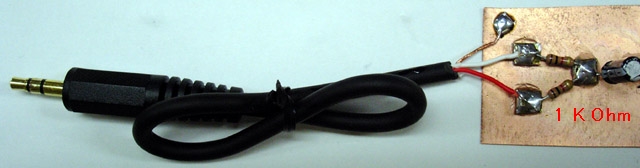
"The earlier model of iPod has an automatic shut-down system in it. When you pull out the plug of your headphone, it automatically stops working. When the left and right channels are short-circuited, the same thing happens. Presumably, you can use a stereo cable and solder the left (white) and right (red) lead together. Please use the left channel lead (white) only. Usually the left output is compatible with mono audio. If you, however, insist to mix the left and right output of your audio source into the transmitter, make a simple "interface" like this." Source: http://www.translocal.jp/radio/micro/howtosimplestTX.html

Radio Station Parts List
1 Resistor 820 Ohm
1 Resistor 4.7 K
1 Resistor 3.3K
1 Resistor 10K
1 Resistor 220K
1 Resistor 1K
1 Capacitor Ceramic Disc 10 pF
1 Capacitor Ceramic Disc .001 uF (102)
1 Capacitor Ceramic Disc .01 uF (103)
2 Capacitor Electrolytic 4.7 uF
1 Transistor 2SC1675 (or 2SC829) Q1
1 Transistor CS9013 Q2
1 Antenna Wire 16"
1 Coil (see text)
1 Electret Microphone
1 Printed Circuit Board
1 Enclosure
1 Printed Panel

Although controls are not necessary, adding a power switch and other capabilities may be desirable.

Spartan Version
On/Off Switch
A very spartan version with rudimentary controls is possible by using a rectangular project box with a hole for the mic protrusion and a hole for the on/off battery switch.

Basic Three Version
On/Off Switch
On the Air LED
Mute Switch
The on/off is a toggle switch wired to turn the 9 volt battery supply on or off.

The next upgrade can include a red LED for "on the air" monitor. This would wire in with the on/off switch and a dropping resistor to the LED.

Another handy feature is an audible mute switch. This would cut out the microphone and switch to a resistor with the same resistance as the microphone.

Deluxe Version
On/Off Switch
On the Air Red LED
Mic Mute
Variable Volume Control
External Sound Input
Signal Strength
Amplifier Monitor
Headset for Amp Monitor
External Power Supply
Switch from 3V, 6V, 9V (regulates output power)
2 Sound Source Mixer
External Antenna 1 or 2 

Band - With different switchable "band" coils, it would be possible to change the transmitting frequency.

Trim - With a variable 0 to 20 pF capacitor, it would be possible to tune the transmitting frequency.

Clock - with added processor
Compass - with added processor

SOURCES
http://www.translocal.jp/radio/micro/howtosimplestTX.html

FM Radio Station Part 5 Index
http://humanoidolabs.blogspot.tw/2013/12/fm-radio-station-part-5-index.html 

Sunday, December 22, 2013

FM Radio Station Part 2 Assembly

Flipped reverse side photo to match component side
MINI FM RADIO STATION  Note top side component placement. Top two holes are for the 9-volt battery clip leads with ground on the left side. The left bottom hole and the bottom right hole are for the antenna connection.
Connections are easily seen when the printed circuit board is back lit, showing the circuit board traces on the reverse side. This makes it easier to match component locations to the schematic diagram.
Schematic diagram for a two stage transistor FM transmitter. Features microphone driven audio input, with tunable frequency range with L1. Operates on a 9-volt battery. Range tests are yet to be determined but the frequency appears to be around 100MHz on the FM band.
BUILD YOUR OWN FM RADIO STATION TRANSMITTER
IN-HOUSE DIY RADIO STATION PART 2


Rotated left to right view for component placement


Work is progressing on the electronic construction of the Lab's two stage exampling FM radio station. Stay tuned to this series of blogs as we supply the details of going on the air, as well as technical info so you can roll your own in-house radio station for fun.

The test transmitter printed circuit board has 17 components mounted and ready for soldering. This blog details the component placement and the circuit traces on the printed circuit board and includes transistor placement guides and a schematic for assembly. Note the two transistor identifications in the illustration showing keyed emitter, base and collector locations. 

The power board uses two transistors, a C1675 K6YC at the right side of the board (see photo above) and a C9013 H049 nearest the microphone. The circuit has one electret microphone input for voice operations and includes one coil, two transistors, two electrolytic capacitors, five ceramic disc capacitors, and five resistors. Not shown is a 9-volt battery clip and the antenna.
Verified leg identification ok
The antenna is only a few inches of wire which minimizes the range for initial testing, and limits use and range of reception to inside the lab room. The electronic project goal is an exampling in-house educational fully functional radio station. More tests will determine the range characteristics more precisely.
Note that some countries and municipalities allow short range transmitters of this type and some do not. Be sure to first check local laws and regulations before proceeding with the project.

The copper printed circuit side of the board with through hole leads ready for hot soldering
Ok to Use: MICRO Data/Japan data
The coil in combination with the parallel capacitor tunes the circuit to a frequency within the FM band.

Frequency trimming is accomplished by stretching or compressing the coil or modifying the value of the ceramic parallel 10 pF capacitor.

Initially the frequency should be in the range of 88 to 108 mHz on the FM band.

Warning - do NOT use USHA India/LGE leg positions
The radio station will have an identical twin backup system for service or parts to remain up and running as necessary.

The cost of the first set of parts is NT$132 (US$4.42) and the backup duplicate parts are NT$120 (US$4.00). Thus far, combined cost is US$8.42 for the hardware.

The transistor leg identification does not agree from one data sheet to the next. See diagrams.

Careful with data sheets for the 2sc1675 transistor as there are discrepancies between the TO92 and TO92b case versions. For example, the equivalent Panasonic 2sc 829 equal to 2sc 1675 as a substitute is in agreement with the transistor placement of emitter, collector, base, therefore this is the arrangement to use.

FM Radio Station Part 5 Index
http://humanoidolabs.blogspot.tw/2013/12/fm-radio-station-part-5-index.html

Friday, October 25, 2013

Brain Cortex Machine Part 4 - Batteries

BRAIN CORTEX MACHINE
BATTERIES - PART 4
BOOT YOUR BATTERY OR GIVE IT THE BOOT?

A market survey of batteries in common stores will reveal the banning of lead acid batteries and the proliferation of alkaline batteries. Reading up on the care and feeding (recharging) of a variety of finicky batteries is complicated and sometimes confusing.

THE FINICKY BATTERY
How many times did a trusty rechargeable battery go dead in your lifetime? A battery is not a simple thing to maintain. It needs levels of charge, specific voltages, specific currents, and specific charging times. It requires a charging cycle involved with timing variants that cannot be too much or too little, too frequent or too infrequent. Plus, to add to the confusion, no two batteries are exactly alike.

UNENDING MISERY HAS COMPANY
It doesn't end there. Nickel metal hydride and nicad batteries have memory, so trying to trickle charge these is either impossible with simple charging or it becomes a complicated set of rules to follow with a smart programmed charger that can not only recharge batteries but sense their condition as well. Even more complicated is that devices drain batteries at different rates and different batteries may drain at different rates even with the same machine.

MAINTAINING BATTERIES
Batteries must also be maintained. Overcharge, undercharge, and the frequency of charging all effect the battery life. Charging may never reach the full capacity of the battery, depending on its age life cycle. Environment is also a factor as batteries can give up the ship when the temperature drops to freezing temps in winter.

NEW TECHNOLOGY SUPER CAP
The dream is to perhaps toss the battery altogether and use another technology like a super super capacitor that can hold a large enough amount of energy so that it can be drained over several days. However, these are often quoted as having the ability to last only minutes or seconds!

SUPER CAP LONGEVITY
We determined the longevity (time in which it can deliver useable power) of a massive super capacitor using calculus dv/dt = i/c. At .03 amps and rounding to 3 volts for the Propeller chip, a 100 F super capacitor can provide only 2.7 hours of drain, while a 500 F super capacitor is more practical at 13 hours. Two of these capacitors in tandem could indeed help the Cortex make it through the night without solar power, providing the caps are fully charged during the day and the batteries have full reserves.

CORTEX REQUIREMENTS
Our requirements are to supply some charging energy from a solar panel that may have periods of lessened energy during the day (as if the sun went behind clouds, or more realistically, a light was turned off inside a room.

During the night, the machine will draw energy and the solar panel will automatically disengage. The battery, or super super capacitor must have enough energy to survive the night. In this situation, we set the bar at 2 days reserve.

TRI LEVEL ENERGY SYSTEM
Now considered is a tri level energy system. The TRI POWER includes the solar cells, super super capacitor, and batteries. Room lighting will activate the solar panel and trickle charge the super capacitor which helps maintain the battery during the night.

CHARGING COMMON ALKALINE
A number of sources describe charging common alkaline batteries, but this is complicated too, as its important to sense the heat level of the battery to ascertain when the charge cycle should be completed. This does not fit into a simple charging scheme.

CONCLUSION
It's still up in the air as to which battery type will work the best with a simple charging system. Alkaline is most common, yet the availability of Nickel Metal Hydride is still a consideration. Lithium Ion has charging requirements that are not met by the solar panel. Lead acid batteries are not available in the size required. Yet, energy supplied to the Cortex must be constant, reliable, or the brain will die and cease to function. This is why the consideration is now from three electric sources - solar, capacitive, and battery. Solar is renewable energy and the capacitor can store it and release it over time. The challenge is now finding a suitable battery.

Brain Cortex Index Part 16

Thursday, July 25, 2013

Propeller Simple Spin Board Part 4 & 5

Experiment 4: crisscross wiring
PART 4 & 5 - IMPROVING RELIABILITY
PROPELLER SIMPLE SPIN BOARD
The Propeller Simple Spin Board will be expanded more in the future. Let's make some preliminary preparations for this and improve its reliability. While in it's RC speed state with RCFAST and RCSLOW, the circuit is already reliable and durable.
Experiment 5: decoupling


However, at higher clock speed, overclocking, with unusual loads or demands, electrical pressures and imbalances occur internally inside the chip, which is also effected with various operational configs. These conditions are not always for the better. However, it's possible to improve the operation of these circuits with external wiring and components.

Although it's a lot of technical mumble jumble jargon to describe it, basically the Propeller needs decoupling capacitors on each side of the dip chip, as close as possible to Propeller pins VSS and VDD, and a special added "criss-cross" wiring. Propeller experts say both the connective wiring and the capacitors (use a .1 uf value) belong to the chip and help to prevent blowing out the PLL circuits inside the chip.

The wiring connects one side of the chip to the other side. Ground VSS on one side (use a green or black wire) is connected to ground VSS on the other side, and power VDD (use a red wire) on one side is connected to power VDD on the other side. Use shortest wires that run directly over the top of the chip. This circuit will balance the chip's internal circuitry and help prevent a condition that could damage the chip. With these improvements installed, the Propeller chip is ready to run extremely fast and do much more than we ever expected. Stay tuned for more.

Another possible requirement involves using the addition of 10uf and 100uf capacitors for when the Propeller is expanded with additional demands. Due to limitations of breadboard pins nearest the chip, these capacitors may or may not connect at the power rails position.