Showing posts with label panel. Show all posts

Thursday, March 19, 2020

Big Brain - Transhuman AI Processor Panel

Big Brain - Transhuman AI Processor Panel
Humanoido and the Medical Lab develop Transhuman Processor Panels

The Transhuman Processor Panel consists of an array of microprocessors with each node in the array containing an insertion needle that can be pushed into the body, thus penetrating the skin to inject machine elements and data collecting devices for advanced AI operations.

Microprocessor elements are polymer encapsulated and include a finite time battery power supply. A very small circuit board accompanies each subset in the panel. In this design, microprocessors and extended Transhuman functions are additive. Each processor commands a function gate and has a self containing needle. The more processors, the more needles that need to inject into the body. Needles are kept in the Transhuman body until the batteries expire at which time the panel array is removed for replacement. AI Machine Processor Panels gradually transform humans into machines, so that humans can control machines and not the other way around.

Monday, December 23, 2013

FM Radio Station Part 3 Assembly & Tips

Fully assembled and ready for testing, the FM transmitter radio station is shown with a potential cabinet housing. Note how the microphone is repositioned top side for ease of positioning inside and through the yellow cabinet.
assembly and tips
HOW TO BUILD YOUR OWN FM RADIO STATION TRANSMITTER PART 3

PARTY TIME!!! Today is a solder party. Get out your guns (soldering guns) and prepare to melt some metal, putting metal (tin) on metal (copper).

Tuning the frequency
By a bit of trial and error plus observation with a nearby FM radio receiver, it is possible to tune the FM transmitter. Using the coil, either expand or compress the wire coils to change the frequency. A closer wire gap give a lower frequency and a loose wider spacing gap gives a higher frequency.

The completed solder side of the printed circuit board with a green loop antenna about 2.75-inches high and a microphone set outwards on one side to facilitate a good fit through the cabinet top. Prime use of this project is to fulfill the authors objective to own and operate a tiny radio station (at the toy level) - in this case, a tiny exampling FM band transmitter that can send broadcasting from one side of the table to the other side.

Apps won't end there as the transmitter can have audio signal input into its stage, such as a Parallax Propeller chip's voice speech synthesizer signal inside the electric brain in a jar, and then transmit a speech signal through the jar, speaking wireless into a nearby radio. Building one transmitter is very cost effective at US$4.
When soldering the electrolytic capacitors and the transistors, use a heat sink on each of the wire leads to prevent component damage from heat.

It is also possible to change the value of the ceramic capacitor which is in parallel with the coil. Some designs use a tunable variable capacitor to do the tuning. In this case, the variable capacitor would have a tunable range from 0 to 10 pF. Since this transmitter has no requirements for specific FM frequencies, the variable capacitor is not needed.

Experiment with the coil spacing first to determine the range. Keep the receiver at distance from the transmitter to minimize the reception of spurious radio signals. Make sure you've found the primary signal which will have the greatest signal strength.

Reference this image showing a different orientation for clarity, to the photo in post part number 2 for circuit path positions. Note the coil spacing to change the frequency to a "quiet spot" on the upper FM dial.
The 10 pF capacitor is set to match the number of turns on the coil. With a greater capacitor value such as 20 or 50, the number of coil turns would be too much.

Antenna Length
First, here are some "getting started" approximate values already calculated for some frequencies. A full wave antenna for 98 Mhz, the center of the FM band, would be 119 inches. A half wave would be 59 inches. A quarter wave antenna for 98 Mhz would be 29 inches long. Try an eighth wave antenna at 14 inches long or a sixteenth wave antenna at 7 inches.

Online Whip Antenna Calculator
http://www.csgnetwork.com/antennagenericfreqlencalc.html
For more precise values, enter the frequency and the online program will calculate half and quarter wavelength whip antenna size. Requires browsers with enabled Javascript. "This calculator is designed to give the vertical length (height) of a particular whip type antenna, or the frequency of it. Enter one (only one) value, the desired frequency or the antenna length in any length field. Click on Calculate and the opposite value will be displayed in feet and inches or frequency in megahertz (Mhz). These are considered as generic calculations and you may wish to use them to learn general information about the antenna structure you are contemplating. Click on Clear Values to prepare for new calculations. Any antenna created with this calculator MUST be fine tuned for VSWR. None of the calculations are rounded or massaged and all calculated results are raw data."

Frequency Stability
The frequency may drift as the battery voltage becomes less. This is expected with this simple design. To offer more regulation, one could use a regulated power supply instead of the battery. The simple design presented here for exampling will use fresh batteries and some frequency drift will be expected. Do not use an AC adapter as these are generally not regulated and introduce interference.

Use with iPod, iPhone, iPad
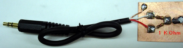
"The earlier model of iPod has an automatic shut-down system in it. When you pull out the plug of your headphone, it automatically stops working. When the left and right channels are short-circuited, the same thing happens. Presumably, you can use a stereo cable and solder the left (white) and right (red) lead together. Please use the left channel lead (white) only. Usually the left output is compatible with mono audio. If you, however, insist to mix the left and right output of your audio source into the transmitter, make a simple "interface" like this." Source: http://www.translocal.jp/radio/micro/howtosimplestTX.html

Radio Station Parts List
1 Resistor 820 Ohm
1 Resistor 4.7 K
1 Resistor 3.3K
1 Resistor 10K
1 Resistor 220K
1 Resistor 1K
1 Capacitor Ceramic Disc 10 pF
1 Capacitor Ceramic Disc .001 uF (102)
1 Capacitor Ceramic Disc .01 uF (103)
2 Capacitor Electrolytic 4.7 uF
1 Transistor 2SC1675 (or 2SC829) Q1
1 Transistor CS9013 Q2
1 Antenna Wire 16"
1 Coil (see text)
1 Electret Microphone
1 Printed Circuit Board
1 Enclosure
1 Printed Panel

Although controls are not necessary, adding a power switch and other capabilities may be desirable.

Spartan Version
On/Off Switch
A very spartan version with rudimentary controls is possible by using a rectangular project box with a hole for the mic protrusion and a hole for the on/off battery switch.

Basic Three Version
On/Off Switch
On the Air LED
Mute Switch
The on/off is a toggle switch wired to turn the 9 volt battery supply on or off.

The next upgrade can include a red LED for "on the air" monitor. This would wire in with the on/off switch and a dropping resistor to the LED.

Another handy feature is an audible mute switch. This would cut out the microphone and switch to a resistor with the same resistance as the microphone.

Deluxe Version
On/Off Switch
On the Air Red LED
Mic Mute
Variable Volume Control
External Sound Input
Signal Strength
Amplifier Monitor
Headset for Amp Monitor
External Power Supply
Switch from 3V, 6V, 9V (regulates output power)
2 Sound Source Mixer
External Antenna 1 or 2 

Band - With different switchable "band" coils, it would be possible to change the transmitting frequency.

Trim - With a variable 0 to 20 pF capacitor, it would be possible to tune the transmitting frequency.

Clock - with added processor
Compass - with added processor

SOURCES
http://www.translocal.jp/radio/micro/howtosimplestTX.html

FM Radio Station Part 5 Index
http://humanoidolabs.blogspot.tw/2013/12/fm-radio-station-part-5-index.html 

Sunday, December 15, 2013

OT & Telescope Control

OT & TELESCOPE CONTROL
Envisioned instrumentation control panel for the new extremely powerful OT Telescope - perhaps the OT designation represents not only "Over the Top" but also "Only Telescope" which can perform all the functions of the previous extremely powerful telescopes.

Looking at existing control instrument panels, the idea in mind for the OT Telescope simply does not exist in the real world. Borrowing from a more imaginative fictional world, several possibilities emerge.

Imagine a singular room, control center, instrumentation array, that includes everything needed for controlling powerful functions. This includes apertures, adjunctives, paradigmics, gravatomics, moleculars, interpolatives, extrapolatives, recyclers, extensions, inferences, gtechs, and power dynamics, all in a single telescope! It could also control the Pro-M Procedural Machine and the remaining list of Monster Machines.

Pro-M Procedural Machine
http://humanoidolabs.blogspot.tw/2013/06/procedural-machine.html

Monster Machines
http://humanoidolabs.blogspot.tw/2013/06/monster-machines.html

Age of the Extremely Powerful Telescope
http://humanoidolabs.blogspot.tw/2013/05/telescope-arsenal.html 

Extremely Powerful Telescopes Update
http://humanoidolabs.blogspot.tw/2013/12/extremely-powerful-telescopes-update.html 

The power reconfigurable OT is the ultimate extreme machine, with more reconfigurable functions than any other extreme machine built to date by the Lab. The extreme machine OT is the most powerful observatory telescope ever conceived by Humanoido Laboratories.

CONTROL PANEL LINKS
Advanced Telescope Control Panel
http://humanoidolabs.blogspot.tw/2013/05/advanced-control-panel.html

Ultra Space Center Upgrade
http://humanoidolabs.blogspot.tw/2013/05/ultra-space-center-upgrade.html

Telescope Control System Wrap Around
http://humanoidolabs.blogspot.tw/2013/04/telescope-control-system-wrap-around-2.html

Telescope Control Systems Bridge
http://humanoidolabs.blogspot.tw/2013/04/telescope-control-system-bridge.html

OT Telescope Controls
http://humanoidolabs.blogspot.tw/2013/12/ot-telescope-controls.html

Projected Mapping Device
http://humanoidolabs.blogspot.tw/2013/06/projected-mapping.html

Power Dynamic Telescope PDT Controls
http://humanoidolabs.blogspot.tw/2013/04/power-dynamic-telescope-controls.html

Power Dynamic Telescope PDT Updated Controls
http://humanoidolabs.blogspot.tw/2013/04/power-dynamic-telescope-updated-controls.html

ULT March Upgrades
http://humanoidolabs.blogspot.tw/2012/03/ult-march-upgrades.html

New controls developed for the AAR
AAR Machine New Controls Arrangement
AAR Control Boiler Plate
AAR Machine Projected Control Mapping

AAR Reality Machine Controls Developed

Extremely Powerful Telescopes Update
Age of the Extremely Powerful Telescope

 
INFERENCE
IET Inference Engine Telescope First Light
IET Inference Engine Telescope Construction
New Expert Inference Engine

IET Telescope Greatest Journey
Inference Engine Icon


GRAVATOMIC

Age of Gravatomic
GGT Gargantuan Gravatomic Telescope
Gravatomic Machine
First Light GGT Gargantuan GravAtomic Telescope

 
MOLECULAR
MMT Molecular Mining the Cradle of Stars

MMT Horsehead Nebula Wide View
Genius Molecular Microscope GMM
MGT Molecular Genius Telescope
MMT Molecular Strip Mining
Interface Molecular Stage Cascader & PGT Telescope

 
ALTERNATE REALITY
Altercated Alternated Reality Machine
Generating Altercated Alternated Reality
AAR Altercated Alternated Reality Machine Establishment


FACEPLATE
GGT Faceplate Control Icon Rework

 
ICONS
Telescope Icons

 
MELTING SPACE AND TIME
Meltdown of Space & Time

 
COMBINATIONS
Imagination, Quantum, Thought Power


CONTROLS

Advanced Control Panel

 
IMAGINATION
Imagination Power


THOUGHT
PGT ET Thought Processor
http://humanoidolabs.blogspot.tw/2013/04/pgt-et-test.html
Thought Processor
http://humanoidolabs.blogspot.tw/2013/04/thought-processor.html
Thought Object Action Amplifier
http://humanoidolabs.blogspot.tw/2012/11/object-amp.html
Is Pure Thought a Virtual Process?
http://humanoidolabs.blogspot.tw/2013/02/is-pure-thought-virtual-process.html
Thought Processing Dimension
http://humanoidolabs.blogspot.tw/2012/10/thought-processing.html

Saturday, December 14, 2013

OT Telescope Controls

Control room - this scene envisions a large enough OT Telescope control room designed to handle all the functions of the previous 14 extreme machine telescopes. The room would need space to include the Big Brain supercomputer and all of its components and supporting divisions. Multiple panels of LCD monitors could show observational OT Telescope views in 14 dynamics. To the left is the containment for the supercomputer.
OT TELESCOPE CONTROLS
OT is the most powerful telescope in the series of extremely powerful telescopes. Representing over the top performance, it includes the functions and capabilities of the previous 14 telescopes.

What is recommended for the telescope systems control panels and instrumentation environment? Perhaps a view from fiction can help envision the dream environment for control of the most powerful telescope, the OT, when it comes into full operation upon completion of assembly with pipe fittings and mountings.

Envisioning star field and particle dynamics analysis - here the telescope operator is selecting the type of field dynamics and adjusting the penetrative depth of sensing and imaging.

One aspect of the new OT telescope is about how to control it and develop instruments and control panels for it. The Promethius photos best illustrate some of the envisioned concepts.

Envisioning global planetary systems and minor objects, including moons, analysis controls and panels
Imagine a singular room, control center, instrumentation array that includes everything needed for controlling powerful functions inclusive of apertures, adjunctives, paradigmics, gravatomics, moleculars, interpolatives, extrapolatives, recyclers, extensions, inferences, gtechs, and power dynamics, all in a single telescope!

Envisioning automatic planetary atmospheric climatology analysis

The power reconfigurable OT is the ultimate extreme machine, powered by a supercomputer, with more reconfigurable functions than any other extreme machine built to date by the Lab. The extreme machine OT is the most powerful observatory telescope ever conceived by Humanoido Laboratories.

Envisioning multi analysis of a singular object suspended in the space time continuum. This type of instrumentation analysis and controls work to analyze and image distant galaxies, global star fields, and space objects from here to infinity. In particular the analysis of dynamics is selectable and multiple results display simultaneously.

LINKS
http://humanoidolabs.blogspot.tw/2013/12/extremely-powerful-telescopes-update.html

Credit: Prometheus

Saturday, November 30, 2013

Brain Cortex Solar Panel Install Part 41

BRAIN CORTEX SOLAR PANEL INSTALL PART 41

The Cortex solar panel was installed inside the brain jar above the power unit's top level. The bottom of the panel is fit to the top ledge of the battery holder, which holds the bottom of the solar panel in place without any hardware. The top of the solar panel has two angle brackets holding it, connected together as shown. The back side of the solar panel has a sticky substance which nicely grips the angle bracket's long extension side. It can also serve as a wire holder as shown.

This is the larger solar panel rated at 3 volts and 120 mA designed to power the brain and trickle charge the batteries during the day. Tests show the panel works in available room lighting.

Index to the Brain Cortex
http://humanoidolabs.blogspot.tw/2013/11/brain-cortex-index-part-16.html

Monday, November 4, 2013

Brain Cortex Solar Cells Part 21

BRAIN CORTEX SOLAR CELL POWER & CHARGING PART 21
Put together solar cells to match a battery pack for charging. The number of cells can determine voltage and supplied amperage. The acquisition of an additional panel for the cortex project enables more brains. Two panels, both 3-volt, have capacities of 60 and 120 mA. Series and parallel combinations are possible to drive a load at 3 or 6 volts and to charge batteries to balance battery pack mAh values. In particular, the 60 mA panel is useful for trickle charging. Although the estimated draw of the Cortex is around 30 mA, the actual value could run much higher depending on cog usage. More tests are in the works.

US$10.31 3v @ 120 mA   $.09 per mA
US$06.04 3v @ 060 mA   $.10 per mA

When using a solar panel for charging batteries, use a blocking Schottky 58117 diode to prevent the solar panel from drawing power from the batteries when there is no light.

Two panels will drive a low power 3 volt Propeller circuit and a 6 volt sensor circuit.

The small single solar panel will drive a smaller brain cortex with one Propeller chip.

Index to the Brain Cortex
http://humanoidolabs.blogspot.tw/2013/11/brain-cortex-index-part-16.html

Brain Cortex Control Panel Part 18

Cortex DVM
BRAIN CORTEX CONTROL PANEL
The cortex is neither animal nor human, but a living machine. It lives within the fine line of a new emerging life form, albeit with a simplified intellect and life.

It can function autonomously and yet have a cortex control panel for human interaction and monitoring. This blog is all about the design of the
Temperature humidity monitor
cortex control panel and some of the features it might include.


First let's establish the duties and functions of a control panel. Here is the current design of useful functions (below).

Photoresistor circuit
It's not out of the question to have a second propeller chip with an additional eight micro processors to do monitoring and tune the control of the energy supply. For example, it could sense battery voltage and initiate recharging. It could sense battery temperature and stop recharging, or detect worn out batteries and ask for replacements. A chronometer could keep track of the machine's age and life intervals.

A night time photo-resistor sensor could induce the machine's sleep cycle and wake it up in the morning or it could determine when to use power from the solar panel or use the solar panel for charging or shut it off in dark conditions.

CONTROLS
BATTERY ON/OFF
SOLAR PANEL ON/OFF
SOLAR CHARGE: ON/OFF
DVM ON/OFF (DIGITAL VOLTAGE METER)
RESET (DUAL SAFETY PUSHBUTTONS)

MONITORED DISPLAY INSTRUMENTS
ELECTRONIC THERMOMETER (AUTOMATIC)

MECHANICAL THERMOMETER (AUTOMATIC)
HYGROMETER (AUTOMATIC)
VOLTAGE METER
 

ADD ON
CAS LIGHT DETECTOR (AUTONOMIC)


WITH 2ND PROPELLER CHIP
LCD 2X16
LIGHT LEVEL (DAY/NIGHT/DARK/BRIGHT)
CHRONOMETER (AGE)
MESSAGE 1 (REPLACE BATTERY)
MESSAGE 2 (TOO HOT)
MESSAGE 3 (TOO COLD)

Index to the Brain Cortex
http://humanoidolabs.blogspot.tw/2013/11/brain-cortex-index-part-16.html

Sunday, November 3, 2013

Brain Cortex Update Part 17

BRAIN CORTEX UPDATE PART 17
MONDAY NOVEMBER 4TH 2013
A journey farther, deeper and longer than ever before into the deepest part of the electronic parts plaza took place yesterday.

— at the heart of this experiment, as part of the Big Brain project, is a special living cortex machine which is designed for human brain to machine transfer, and to extend the life of both symbiotic human and machine, in the most simplistic way, yet representative of greater things to come —
 
There's no doubt about the sacrifices made to keep this project going. The ravages of this often arduous journey have exceeded the extreme physical limits of any human — i.e. being thrown around on a violent bus with no shock absorbers, having a leg torn, a hip twisted and sprained, bruised and being trampled by enraged stampeding crowds of thousands of people, becoming car sick on the taxi with the driver from Hell, catching flu germs from thousands of people in small hot humid places, becoming lost amidst twisting streets with no rhyme or reason and maps that don't properly match the city jungle, and walking (5 miles) to reach a futuristic home in the sky. This also includes walking up six stories and back down again, and back and forth (yoyo effect), in the skyscraper of a parts plaza, because someone decided to turn off the elevators and escalators to save money.

However, on the flip side of the coin, the rewards are totally spectacular and great, mind boggling, like a great fantastic dream from the future, and the climb upwards from level 1 to level 5 inside the electronics parts plaza was like traversing the stairway to Heaven, as every electronic part in and beyond imagination seemed to be available.

The Cortex project now has the parts it needs and remains fully funded by Humanoido Laboratories and supporters and investors are fully in favor of ramping up and increasing the project to include not only the current cortex, but a possible array of new sophisticated and simplified demonstrative cortex' and a ramping up of human brain to machine transfer experiments.

The parts rewards this time include a new solar panel for a smaller test cortex, perhaps a micro cortex (smaller than the mini cortex) to be placed in the smallest jar, and a multiple power cell mount array for ten individual cells for the large cortex. It will also serve for other experiments and directly drive a Parallax Propeller chip.

A large number of brass hardware spacers were obtained to attach the power cell mounts to the jar walls. Phenolic insulators were obtained in a quantity large enough to earthquake-proof the jar to a higher level.

An instrument panel was obtained to read the voltage level and display it on a digital readout. This has two leads for the supply to power it and two leads to be used for the voltage input. Since the device has 3 leads, one is shared with the two inputs.

One challenge is reading the Chinese instruction page for wire connections because no schematic is provided. The device instructions are not online and so a translator is needed, making some delay for work on the control panel.

Brain Cortex Index Part 16