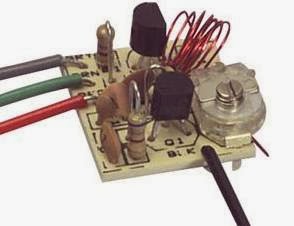
FM RADIO STATION MICROPHONIC PART 25
HOW DO YOU TRANSMIT VOICE WITHOUT A MICROPHONE?
This is a two
transistor circuit that makes up a wireless FM radio transmitter with a
remarkable feature - it transmits voice without a microphone!
It uses a floppy coil that moves upon receiving the vibrations from speech or other sources.
"This means it will vibrate when bumped and will even pick up sounds such as talking, music and footsteps and transmit audio just like a microphone.
Forget the phone lines as they are not needed for this example. Build the circuit and use 7 turns of thin wire on an 8-10mm pen and see how the coil picks up every sound in the room. Simply connect a 9v supply and the circuit starts broadcasting. The coil should be 6t and 3mm diameter, using 0.5mm enamelled wire."
Source
http://www.talkingelectronics.com/projects/Spy%20Circuits/SpyCircuits-3.html
BIG BRAIN made by Humanoido is a giant intelligent AI machine. Over twenty years in the making, living and sentient, approaching one trillion processors/constructs. Join us in the exciting adventure as it continues to evolve!
Showing posts with label spy. Show all posts
Tuesday, December 31, 2013
FM Radio Station Microphonic Part 25
Labels:
big,
brain,
bug,
fm,
humanoido,
mic,
microphone,
microphonic,
part 25,
radio,
spy,
station,
transmit,
transmitter
FM Radio Station Notes Part 24
FM RADIO STATION NOTES PART 24
TUTORIAL: How Radio Waves are Produced
http://www.youtube.com/watch?v=aAcDM2ypBfE#t=186
FM TRANSMITTER
As a reference to going even smaller and more simple, this schematic shows possibly the most simple one transistor FM radio voice transmitter design, using a common 2N2222 transistor and only three capacitors and two resistors. There's only 7 electronic parts total to this assembly plus batteries and the antenna. A power on/off SPST switch should be added to the schematic.
Parts List
R1 Resistor 4.7K
R2 Resistor 220 ohms
C1 Capacitor .01uf
C2 Capacitor 33pf
C3 Capacitor 6.8pf
L1 Coil
Electret Microphone
2 - 1.5 Volt Battery
A slightly modified version is at this web site:
http://www.sentex.ca/~mec1995/circ/fmt2.htm
http://www.sentex.net/~mec1995/circ/circuits.htm
FM RECEIVER
The video also includes a schematic diagram for a very simple matching two stage FM radio receiver. This battery driven radio has only two transistors, amounting to 6 electronic parts plus batteries, switch and antenna.
Parts List
R1 Resistor 12K
C1 Capacitor 220n
T1, T2 Transistor BF199
C Variable Capacitor
3 Volt Battery
SPST Switch
Earphones
Antenna
BF199 transistor data sheet
http://pdf1.alldatasheet.com/datasheet-pdf/view/2947/MOTOROLA/BF199.html
MOST SIMPLE FM TRANSMITTER
The simple FM transmitter circuit shown above is a spinoff of this project. It uses only one resistor, one capacitor, one transistor and one coil. The article is found all over the web. It has no microphone but the coil is so microphonic that it will pick up noises in the room via vibrations on a table. The circuit does not have any section that actively tunes the frequency. The transistor turns on via the 47k resistor and this puts a pulse through the 15 turn winding. The magnetic flux from this winding passes through the 6 turn winding and into the base of the transistor via the 22n capacitor. This pulse is amplified by the transistor and the circuit is kept active. The frequency is determined by the 6 turn coil. By moving the turns together, the frequency will decrease. The circuit transmits at 90MHz which is at the low end of the 88 to 108 MHz FM band. It has a very poor range and consumes 16mA.
http://www.circuitlab.org/2013/02/schematics-easy-build-rf-transmitter.html
http://skema-elektronik.blogspot.tw/2011_02_01_archive.html
http://circuit-diagram.hqew.net/Simplest-RF-Transmitter-circuit-diagram_4095.html
http://www.talkingelectronics.com/projects/Spy%20Circuits/SpyCircuits-1.html
This Google search link will find a lot more simple FM radio transmitter schematics and projects.
SIMPLEST FM TRANSMITTER
Here's another link to a project claiming also to be the simplest FM transmitter ever made.
http://circuitsdiy.com/the-simplest-f-m-transmitter-ever-made/
This circuit has audio input and needs only 2 resistors and 3 capacitors plus a coil and transistor.
"For input from low power output devices, such as mobile, computer’s sound card, the value of the unlabeled capacitor is 0.1 or 104. For higher wattage outputs, the value is 0.01 or 103. An optional microphone pre-amp can be also added in this circuit to enable it transmit voice directly."
ANTENNA
One idea to create the small transmitter antenna is to use a small wheel bicycle used spoke from a children's bike available from a bike shop probably for free.
How to Change a Dark Detector into an FM Transmitter
http://www.buildcircuit.com/fm-transmitter-and-dark-sensor/
A dark sensor can be converted to a simple FM transmitter using a similar schematic layout.
The dark sensor will light the LED as the output indicator. The transmitter substituted a microphone for the LDR.
FM TRANSMITTER
This FM transmitter is very sensitive and it has transmitting range of 30 meters with a 9-volt battery. Reducing battery power will reduce transmitter range.
Comments given at the link about the transmitter
The circuit may work but it relies on a “Q-factor” from the coil and capacitor in the tank circuit to produce a high voltage.
This high voltage gives the circuit a good range. Firstly the coil and capacitor should be near each other. The coil should not have long leads. and a 22n capacitor should be across the supply to give the circuit better performance. The value of C2 is too high. It should be 10p. The coil should be 5 turns. The electret mic should not be connected directly to the base of the transistor.
TUTORIAL: How Radio Waves are Produced
http://www.youtube.com/watch?v=aAcDM2ypBfE#t=186
FM TRANSMITTER
As a reference to going even smaller and more simple, this schematic shows possibly the most simple one transistor FM radio voice transmitter design, using a common 2N2222 transistor and only three capacitors and two resistors. There's only 7 electronic parts total to this assembly plus batteries and the antenna. A power on/off SPST switch should be added to the schematic.
Parts List
R1 Resistor 4.7K
R2 Resistor 220 ohms
C1 Capacitor .01uf
C2 Capacitor 33pf
C3 Capacitor 6.8pf
L1 Coil
Electret Microphone
2 - 1.5 Volt Battery
A slightly modified version is at this web site:
http://www.sentex.ca/~mec1995/circ/fmt2.htm
http://www.sentex.net/~mec1995/circ/circuits.htm
FM RECEIVERThe video also includes a schematic diagram for a very simple matching two stage FM radio receiver. This battery driven radio has only two transistors, amounting to 6 electronic parts plus batteries, switch and antenna.
Parts List
R1 Resistor 12K
C1 Capacitor 220n
T1, T2 Transistor BF199
C Variable Capacitor
3 Volt Battery
SPST Switch
Earphones
Antenna
BF199 transistor data sheet
http://pdf1.alldatasheet.com/datasheet-pdf/view/2947/MOTOROLA/BF199.html
MOST SIMPLE FM TRANSMITTER
The simple FM transmitter circuit shown above is a spinoff of this project. It uses only one resistor, one capacitor, one transistor and one coil. The article is found all over the web. It has no microphone but the coil is so microphonic that it will pick up noises in the room via vibrations on a table. The circuit does not have any section that actively tunes the frequency. The transistor turns on via the 47k resistor and this puts a pulse through the 15 turn winding. The magnetic flux from this winding passes through the 6 turn winding and into the base of the transistor via the 22n capacitor. This pulse is amplified by the transistor and the circuit is kept active. The frequency is determined by the 6 turn coil. By moving the turns together, the frequency will decrease. The circuit transmits at 90MHz which is at the low end of the 88 to 108 MHz FM band. It has a very poor range and consumes 16mA.
http://www.circuitlab.org/2013/02/schematics-easy-build-rf-transmitter.html
http://skema-elektronik.blogspot.tw/2011_02_01_archive.html
http://circuit-diagram.hqew.net/Simplest-RF-Transmitter-circuit-diagram_4095.html
http://www.talkingelectronics.com/projects/Spy%20Circuits/SpyCircuits-1.html
This Google search link will find a lot more simple FM radio transmitter schematics and projects.
SIMPLEST FM TRANSMITTER
Here's another link to a project claiming also to be the simplest FM transmitter ever made.
http://circuitsdiy.com/the-simplest-f-m-transmitter-ever-made/
This circuit has audio input and needs only 2 resistors and 3 capacitors plus a coil and transistor.
"For input from low power output devices, such as mobile, computer’s sound card, the value of the unlabeled capacitor is 0.1 or 104. For higher wattage outputs, the value is 0.01 or 103. An optional microphone pre-amp can be also added in this circuit to enable it transmit voice directly."
ANTENNA
One idea to create the small transmitter antenna is to use a small wheel bicycle used spoke from a children's bike available from a bike shop probably for free.
How to Change a Dark Detector into an FM Transmitter
http://www.buildcircuit.com/fm-transmitter-and-dark-sensor/
A dark sensor can be converted to a simple FM transmitter using a similar schematic layout.
The dark sensor will light the LED as the output indicator. The transmitter substituted a microphone for the LDR.
FM TRANSMITTERThis FM transmitter is very sensitive and it has transmitting range of 30 meters with a 9-volt battery. Reducing battery power will reduce transmitter range.
Comments given at the link about the transmitter
The circuit may work but it relies on a “Q-factor” from the coil and capacitor in the tank circuit to produce a high voltage.This high voltage gives the circuit a good range. Firstly the coil and capacitor should be near each other. The coil should not have long leads. and a 22n capacitor should be across the supply to give the circuit better performance. The value of C2 is too high. It should be 10p. The coil should be 5 turns. The electret mic should not be connected directly to the base of the transistor.
Sunday, September 22, 2013
Robot Explorer Log 8 Wireless Camera
A WIRELESS CAMERA SYSTEM
FOR ROBOT EXPLORER - Log 8
Robot Explorer is a new space robot designed under the Big Brain Initiative at Humanoido Labs, to explore new worlds at the outer fringes of the solar system.
One of the most important parts of the robotics system is the wireless camera. The camera will transmit live images from the surface of the planet or moon on its own channel and allow humans to watch as the robot explores a new world.
OVERVIEW
It took three months to design and gather all the parts necessary to build the wireless camera system for the Robot Explorer prototype. This system sends a TV color image by a 1.2 GHz frequency signal up to a long range base station, located up to 1,000 meters (.63 mile) in distance. The signal reaches the receiver, is decoded into the A/V NTSC composite 1V pp format and is fed to the TV's A/V input jack.
WIRELESS CAMERA SYSTEM
The system consists of a miniature camera, camera image transmitter, camera and transmitter battery power pack, receiver and TV monitor. The TV monitor and receiver are located at the tracking station and the other parts remain within the robot. The modules are made in Taiwan. The units are prewired at the store by the store owner. It's apparent, the harness combines the battery plug with both transmitter and camera. The store owner wired the battery pack, which was purchased from another store, and provided the required power barrel end plug. Purchasing the system at the A/V store provided extra service, i.e. the entire system was wired, set up and tested. The other benefit, this is a take home system with no waiting for shipment for an unknown "working or not working" package that would require some assembly.
POSITIONING
The camera, battery pack, and transmitter are located on the robot. The receiver and TV are located at the tracking and telemetry station.
PURCHASING
The system was purchased locally at the A/V parts store. The owner provided service for putting the system together and testing it. He also wired the battery pack (purchased from another store), provided the power barrel jack, and tested it at no additional charge. Information is gathered from the store owner and a variety of sources.
MEASURING THE TRANSMITTER
The camera 1.2 GHz transmitter was measured with a frequency meter and actual respective channel frequencies were 1080, 1120, 1160 and 1200 Mhz.
COST IN NT$
$1,700 for the camera
$1,200 for the camera transmitter
$1,000 for the receiver
$2,500 for the TV monitor
$432.0 for batteries
$30.00 for the battery holder
CAMERA
Image Sensor ⅓” Sony Super HAD CCD (Sony SS11)
Horizontal Resolution 420 TV lines
Medium Resolution
S/N Ratio more than 48dB (AGC off)
Auto backlight compensation
3.6mm Adjustable lens
LUX (.5 LUX @ f/1.2) Color
Effective Pixels NTSC 512(H) x 492(V)
Power Supply DC 12V
Power Draw @ 110 mA
Video Out 1Vp-p 75 ohm
Operating Temperature -10 deg. C to +55
Storage Temp -30 C to +60
Dimension 35mm x 35mm (less swivel base)
Weight 240g
Model (IAS-35XT42) Taiwan
http://www.intex.com.tw/detail.php?PID=52
TRANSMITTER
Frequency 1.2 Ghz (1200 Mhz)
Channels 4 (increments of 40)
Output Power 700mW
Range (1000m line of sight)
Battery 12 volt
Weight
Dimensions
RECEIVER
Receiver TR-1500
Power 12Vdc
4 channels
CH1 = 910MHz, CH2 = 980MHz, CH3 = 1010MHz, CH4 = 1040MHz
AV Video Out NTSC 1V pp composite
1.2GHz
Video input : RCA*1 composite video 1 Vp-p, 75Ω
Video output : RCA*1 composite video 1 Vp-p, 75Ω
Audio output : RCA*1
Antenna : Dipole
Operation Temperature : -5degree to 45 degree
Operation Humidity 5% TO 85%
Dimensions : 130mm*80mm*23 mm (without antenna)
Weight : 263 g
Consumption : 12VDC 350mA
Connection : White - Audio, Yellow - Video
CAVEAT
Even if the cable looks good with shrink wrap covering the connection, it's likely the two wires were only twisted together and not soldered. If an intermittent open connection occurs, it will not be surprising. Just strip the tubing and wiring, add new tubing, solder it together and shrink the tubing.
LINKS
http://www.dronesvision.net/en/wireless-av/44-racewood-900mhz-wireless-av-receiver-vrx-for-fpv-wireless-cctv-cameras-green-label.html
http://www.goodluckbuy.com/cctv-900tr-1500-0-9ghz-a-v-mini-receiver-box-manual-4ch.html
http://www.rc-cam.com/forum/index.php?/topic/3672-comtech-tuner-module-upgrade/
FOR ROBOT EXPLORER - Log 8
Robot Explorer is a new space robot designed under the Big Brain Initiative at Humanoido Labs, to explore new worlds at the outer fringes of the solar system.
One of the most important parts of the robotics system is the wireless camera. The camera will transmit live images from the surface of the planet or moon on its own channel and allow humans to watch as the robot explores a new world.
OVERVIEW
It took three months to design and gather all the parts necessary to build the wireless camera system for the Robot Explorer prototype. This system sends a TV color image by a 1.2 GHz frequency signal up to a long range base station, located up to 1,000 meters (.63 mile) in distance. The signal reaches the receiver, is decoded into the A/V NTSC composite 1V pp format and is fed to the TV's A/V input jack.
| Specification page for the SONY CCD |
The system consists of a miniature camera, camera image transmitter, camera and transmitter battery power pack, receiver and TV monitor. The TV monitor and receiver are located at the tracking station and the other parts remain within the robot. The modules are made in Taiwan. The units are prewired at the store by the store owner. It's apparent, the harness combines the battery plug with both transmitter and camera. The store owner wired the battery pack, which was purchased from another store, and provided the required power barrel end plug. Purchasing the system at the A/V store provided extra service, i.e. the entire system was wired, set up and tested. The other benefit, this is a take home system with no waiting for shipment for an unknown "working or not working" package that would require some assembly.
POSITIONING
The camera, battery pack, and transmitter are located on the robot. The receiver and TV are located at the tracking and telemetry station.
PURCHASING
The system was purchased locally at the A/V parts store. The owner provided service for putting the system together and testing it. He also wired the battery pack (purchased from another store), provided the power barrel jack, and tested it at no additional charge. Information is gathered from the store owner and a variety of sources.
MEASURING THE TRANSMITTER
The camera 1.2 GHz transmitter was measured with a frequency meter and actual respective channel frequencies were 1080, 1120, 1160 and 1200 Mhz.
COST IN NT$
$1,700 for the camera
$1,200 for the camera transmitter
$1,000 for the receiver
$2,500 for the TV monitor
$432.0 for batteries
$30.00 for the battery holder
![]() |
| Showing the battery pack, CCD camera with adjustable lens and the 1.2GHz transmitter. This is a custom made cable to join the camera and transmitter to a 12-volt battery power suppy. |
Image Sensor ⅓” Sony Super HAD CCD (Sony SS11)
Horizontal Resolution 420 TV lines
Medium Resolution
S/N Ratio more than 48dB (AGC off)
Auto backlight compensation
3.6mm Adjustable lens
LUX (.5 LUX @ f/1.2) Color
Effective Pixels NTSC 512(H) x 492(V)
Power Supply DC 12V
Power Draw @ 110 mA
Video Out 1Vp-p 75 ohm
Operating Temperature -10 deg. C to +55
Storage Temp -30 C to +60
Dimension 35mm x 35mm (less swivel base)
Weight 240g
Model (IAS-35XT42) Taiwan
http://www.intex.com.tw/detail.php?PID=52
TRANSMITTER
Frequency 1.2 Ghz (1200 Mhz)
Channels 4 (increments of 40)
Output Power 700mW
Range (1000m line of sight)
Battery 12 volt
Weight
Dimensions
RECEIVER
Receiver TR-1500
Power 12Vdc
4 channels
CH1 = 910MHz, CH2 = 980MHz, CH3 = 1010MHz, CH4 = 1040MHz
AV Video Out NTSC 1V pp composite
1.2GHz
Video input : RCA*1 composite video 1 Vp-p, 75Ω
Video output : RCA*1 composite video 1 Vp-p, 75Ω
Audio output : RCA*1
Antenna : Dipole
Operation Temperature : -5degree to 45 degree
Operation Humidity 5% TO 85%
Dimensions : 130mm*80mm*23 mm (without antenna)
Weight : 263 g
Consumption : 12VDC 350mA
Connection : White - Audio, Yellow - Video
CAVEAT
Even if the cable looks good with shrink wrap covering the connection, it's likely the two wires were only twisted together and not soldered. If an intermittent open connection occurs, it will not be surprising. Just strip the tubing and wiring, add new tubing, solder it together and shrink the tubing.
LINKS
http://www.dronesvision.net/en/wireless-av/44-racewood-900mhz-wireless-av-receiver-vrx-for-fpv-wireless-cctv-cameras-green-label.html
http://www.goodluckbuy.com/cctv-900tr-1500-0-9ghz-a-v-mini-receiver-box-manual-4ch.html
http://www.rc-cam.com/forum/index.php?/topic/3672-comtech-tuner-module-upgrade/
Subscribe to:
Posts (Atom)


