Showing posts with label tiny. Show all posts

Saturday, May 30, 2015

Tiny Telescope Observatory & Aperture Stretching

TINY TELESCOPE OBSERVATORY & APERTURE STRETCHING


The tiny telescope observatory is a dream for 16 years. The goal is to take a tiny telescope of precision optical quality, about 2 to 6 inches in diameter, and magically stretch it into a 20 to 60-inch telescope using high technology.

This is a fantastic story that's just beginning because a tiny telescope can now make big discoveries, after having aperture stretching. Studying the planets and moons, or deep sky, can lead to profound observational data and breathtaking imagery.
Fake big ETX Source
The core of the stretching technique dates back many years to a time when Humanoido was in Junior High School and needed a method to increase the performance of a high quality 4.25-inch diameter reflector telescope.
Several techniques were invented, some which are additive, to make a small telescope into a large telescope.

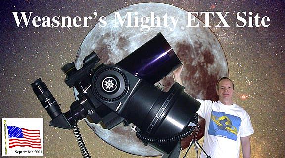
Meade ETX-60AT & ETX-70AT Telecopes
The first technique converted the 4.25 inch telescope into a 42.5-inch telescope using non digital means. As an example of this performance, when photographing Jupiter, the moon Ganymede came into view so it was captured too. To unbelievable surprise, Ganymede had surface structure visible in the photos and the stretching technique was etched in stone. 
The second technique uses an electronic invention to double the size of the telescope. This digital technique completely replaces the first non-digital technique which has its roots in chemical film based processing.
The third technique depends on the telescope design. A refractor is generally known to perform like a reflector telescope twice its size, because it has no central obstruction. The reflector telescope will be the base criteria.
The telescope is also found on Amazon.com
In conclusion, a Meade 60AT with a 60mm aperture will perform like a 120mm aperture, or 4.7-inches. Then applying Humanoido's electronic technique, this telescope will become a 47-incher. This is really fantastic.

MX-1 iPhone adapter
If you wanted to buy a 47 inch telescope, it might cost 1.1 million dollars and take up space bigger than a house. You can see the cost effectiveness of this project. The Meade ETX-60AT telescope is currently as low as $65 on Ebay.

Why the Meade ETX-60AT When Larger Scopes Are Available?
The telescope was chosen because it's a high resolution refractor without a central obstruction that can make it perform like a reflector telescope with twice the aperture. It was chosen for its diminutive size, perfect for a tiny observatory, or a tiny car observatory. It was also chosen for its computerized GOTO functions and simplistic ALT-AZ mounting and drive.

Wednesday, September 24, 2014

Space1 Magazine Issue 3

SPACE1 MAGAZINE ISSUE 3

Space1 has completed its issue number two magazine and begun work on issue #3 Sept. - Dec. 2014. Issue three is already spectacular with articles about the Space Machine, a tiny space station, and modifying a keychain camera.


Saturday, January 11, 2014

Tiny Space Station

Tiny orbital flights with the tiny rocket and tiny space shuttle to the Moon for space tourism are a part of the Tiny Space Program's proposals. Also proposed are visits to the tiny outpost in space otherwise known as the tiny space station. "Apollo 16 metric camera image of the Moon's eastern limb and far side. The lower left part of the image shows a portion of the moon visible from Earth. The dark area at the 8:00 position on the edge is Mare Crisium. To the right of that is Mare Smythii. The upper right area shows the heavily cratered lunar far side. The Moon is 3475 km in diameter and North is at 10:30 in this image. (Apollo 16, AS16-3021)" SOURCE
DEVELOPING A TINY SPACE STATION COMPLETE WITH A TINY SPACE SHUTTLE 
with potentials to launch and conduct flights to the Moon on a routine basis

TINY SPACE PROGRAM
The tiny space program operations conducted by the Big Brain machine space initiative and Humanoido Laboratories could also include civilian tourist flights to the matching tiny space station and outpost in space, Earth orbit, Moon, space sightseeing to the ISS International Space Station, conduct a rescue mission, or simply offer lower cost suborbital flights. The example illustrates the Golden Spike's Moon Landing Plan from space.com (which may have robot based occupants) as an example only, due to its smaller size and capacity, as well as its simple approach to a lunar mission. The Humanoido Lab approach is smaller than this

The current plan for Tiny Shuttle is to offer tourist orbits of the Moon. A trip to the Moon would be very dramatic upon arrival. In the future, colonists will live on the Moon and the tiny space program could offer the deployment of supplies and conduct orbital studies to find best locations for water and mineral mining. Small packages could be transported to the lunar colonists, containing new seeds for growing food, and special selected items as needed.

How tiny is Tiny? We anticipate two levels of the Tiny program. The first is exampling tiny and the second is one man capacity tiny.

Sunday, November 17, 2013

Brain Cortex Simulator Machine Part 33c

BRAIN CORTEX SIMULATOR MACHINE part 33c

Created 6 Feb 2007

Discovered from the archive crypt, The Cortex Simulator Project encompasses the development of a tiny machine program to emulate one facet of the human brain Cortex. This represented the first beginning work started to construct and understand a machine brain cortex. As the project was successful, the tiny machine program was expanded and developed as an application for humanoid robotics.

It took a time span of almost 3 years, from 2007 to 2009 for the construction of an actual cortex that was embedded in a super computer.

http://humanoidolabs.blogspot.tw/2013/11/the-undiscovered-brain-cortex.html

Index to the Brain Cortex
http://humanoidolabs.blogspot.tw/2013/11/brain-cortex-index-part-16.html

Sunday, October 20, 2013

Propeller Chip Tiny Digital Recorder

TINY DIGITAL RECORDER USING A
Demo Board rev D, E, F, click to enlarge
PROPELLER CHIP VOICE RECORD & PLAYBACK

Set up a Parallax Propeller chip with microphone in and speaker out (or run code on the Parallax Propeller Demo Board) to enable a digital recorder for a few seconds of sound record and playback, much like a unit sold at Radio Shack.

"It records one second of sound into the Prop's RAM (no SD card etc. needed), then plays that sound when another sound exceeds a sound threshold."

DISCOVERY POST
http://forums.parallax.com/showthread.php/105292-Parrot-Auto-voice-record-and-playback

The code is provided by Raymond at the Parallax Forum. "It uses the demo board's microphone (voice activated) to record·a second of audio. Then, it plays it back out the speakers a second later. After this, it will randomly either repeat or record again. Of course, this idea could be extended into a WAV recorder... This works good for recording something short like "Boo!" for Halloween effects. Nothing else is needed to store the record except the Prop chip itself. You don't have to have it say "boo" to be a Halloween feature... just a mysterious parrot.. unseen, but heard will offer up lots of fun. Just make sure that the mysterious parrot is loud enough, but coming from an impossible to determine source (maybe a ceiling speaker). Play with the timing and have it be a weird echo of sorts."

File Type: zip Parrot_8bit.zip‎ 18.5 KB

Beau Schwabe offers a variation with ECHO capabilities used in a Halloween application. "I was playing around with this object a little bit tonight for a Halloween prop, and I figured out a way to really sustain the echo for long periods of time (about 20 seconds). When you adjust the bit resolution, you can really get some funky robotic to large auditorium sound effects..."

http://forums.parallax.com/showthread.php/97402-Microphone-to-Headphones-Object?p=681482&viewfull=1#post681482

Propeller Echo Test - Happy Halloween.zip‎ 1.89 MB 

PropellerEchoTest_laugh.zip‎ 1.89 MB
Propeller Echo Test.spin‎ 3.9 KB
PropellerEchoTest_8.zip‎ 568.2 KB
PropellerEchoTest_10.zip‎ 591.3 KB

For downloading a schematic that includes revision G:
http://www.parallax.com/sites/default/files/downloads/32100-Propeller-Demo-Board-Schematic-RevG_0.pdf

Microphone-to-VGA demo in the OBEX. http://obex.parallax.com/object/80 

Monday, October 14, 2013

TSS Tiny Stamp Supercomputer

Tiny Stamp "Supercomputer" TSS
The World's 1st Hand-Held BASIC Stamp "Supercomputer"


by Humanoido

This is the TSS Tiny Stamp Supercomputer that appeared in Robot Magazine.


In the January/Feb. 2011 issue of Robot magazine, page 16 in the LERN section you saw the BASIC Stamp Supercomputer. This is actually the new portable project TSS - Tiny Stamp Supercomputer that uses seven cores and a BELKIN USB HUB. In the same issue of Robot magazine, you can see two more articles about robot humanoids in China.

(demonstration of basic principles to take some characteristics of a supercomputer, in particular the notion of larger multiples of relatively simple processors communicating over a common bus, each doing a portion of a task in parallel)

The BASIC Stamp Clustered Supercomputer series is a number of hobby projects to design BASIC Stamp microcontroller clusters with more power compared to a single Stamp. The name supercomputer is indicative of the increase in power by comparing to a single stamp.

Absolutely the most powerful in terms of the smallest footprint with many tiny Stamp networked processors. It’s a cluster of Stamps in your hand. Has its own book with 30 fun projects. Includes Architecture, Assembly, Programming, Tutorial, Applications, Complete Code. The TSS has multiple computers, LCD monitor, radio transmitter, receiver, speakers, breadboard real estate and a 64K EEPROM memory board, all interfaced to a tiny Hub. The TSS Stamp supercomputer is so small it will fit into a soup bowl or coat pocket. Includes special features such as hardware programming "on the fly."

The Tiny Stamp Supercomputer (TSS) is the first hand-held Basic Stamp Supercomputer. It’s the smallest in the series of Parallax Basic Stamp supercomputer projects by Humanoido. It is also the first USB Stamp supercomputer, made possible by the innovative BS1USB board made by Parallax. This project compliments the Basic Stamp Supercomputer (BSS), the Stamp Baby Supercomputer (SBS/Baby), and the Propeller (MELS) supercomputer.

Price & Disclaimer
This is a pure hobby project for my personal enjoyment and use only, and is not for sale. If the project does not satisfy your requirements, keep in mind that it was not intended to do so. This is not a product, and the descriptions are offered as is, in whatever degree or lack of degree of completeness for your inspiration and ideas. Good luck!


ABOVE: This is a view of the new “hand-held” Tiny USB Stamp Supercomputer TSS during construction. Seven computers, LCD monitor, radio transmitter, receiver and a 64K EEPROM memory board are interfaced to a Belkin USB Hub. The Stamp supercomputer is so small, it will fit into a soup bowl or Parka coat pocket. The yellow wires are for the port-to-port one wire interface. The black wires are adjoining Vss and red wires are Vdd. White represents a serial signal wire. By comparison, the American penny shows the extreme tiny features of the TSS Tiny Stamp Supercomputer! 

Tiny includes an optional serial “green screen” by Parallax, pulling a whopping 20ma, the most power hungry device in this ultra tiny array. This is actually a miniscule power draw. In fact, the supercomputer consumes so little power, it would be a good candidate for solar power. Note the position of two computers located in the front behind the LCD. The remainder computer array is located to the rear of the USB hub.

How to Build Tiny - Building Up the USB Hub First build up the USB Hub by attaching three small solderless breadboards using their self adhesive sticky tape on the back side. Locate the breadboards according to the photo. Each breadboard side has 17 rows of 5 pins for 85 holes to a side, giving a total of 170 holes perboard. This makes a total of 510 wire and component mounting positions with all three breadboards. The hub has eight lights (one red power light and seven green LEDs indicating connected USB devices). The USB Basic Stamps have seven green LED lights indicating power on status. Tiny has a total of fifteen status lights.

Tiny is a powerful array of seven BS1USB computers connected to a Belkin HI-Speed USB 2.0 powered 7-port Hub. The 7-port Belkin Hub’s advantage is its ability to provide considerable power to the USB devices (Stamps) simultaneously, and peripherals, not drawing from the laptop’s limited power source. Each tiny Stamp PCB contains vital components (processor, clock source, memory, power regulator).
Tiny packs a punch in a small package and is loaded with features and peripherals. Let’s take the grand tour!

Affixed to the high speed USB hub are seven Parallax BS1USB computers, seven piezo speakers, a Parallax 433 Mhz radio transmitter, a matching receiver, Parallax serial LCD green screen monitor, eight pushbutton keypad, DS1620 Digital Thermometer, Parallax EEPROM non-volatile memory board, and a Parallax QT113-D Touch Sensor. Tiny can access other Stamp Supercomputers located within a full city block, communicate with a Base Station, and cluster together entire Stamp supercomputers located around the city!

The Tiny Stamp Supercomputer blueprints show schematics for the base unit. This contains seven clusters of BS1USB computers interfaced to a powered USB hub for programming. After all seven computers are programmed, the USB cable from the Hub to the Laptop is removed. The wall power supply to the hub remains on. Compare the new Tiny Stamp Supercomputer blueprints (seven computers) with the networked 3D Stamp Computer (three computers).

Historically, the 3DSC is the forerunner of Tiny, and the first 3DSC Stamp clustered array to incorporate the BS1. The BS1 is filled with advantages, in terms of tiny power consumed, tiny footprint, large number of ports, and large capabilities for more powerful hobby BASIC Stamp clustered machines.

Wiring & Assembly Step by Step
Wiring is accomplished from port to component and component to port using the computer’s on board SIP socket and small gauge wire, plus the three small Parallax solderless breadboards attached to the Belkin Hub housing. This will support numerous additional supercomputer components and sensors.

( ) Plug in seven BS1USB computers to the Belkin 7-port hub
( ) Run a wire from P0 Computer 1 to P0 on Computer 2. Repeat to Computer 7.
( ) Connect all grounds together with jumper wires (Vss)
( ) Connect all +5 volts together (Vdd)
( ) Consult the schematic to wire the peripherals

Tiny Stamp Supercomputer Parts List
Parts for the Main Supercomputer
7 - Parallax BS1USB Board
1 – Belkin Powered High Speed USB 2.0 Hub
3 – Parallax Solderless Breadboards
4 – Rubber Bands
30 – Pin to Pin Jumper Wires
Peripherals Used in this Project, from Parallax
7 – Five Volt Piezo Speakers
1 – Green Screen Serial LCD
1 – 433 Mhz Radio Transmitter
1 – 433 Mhz Radio Receiver
1 – 64K EEPROM Memory Board
Parts for Project Applications
1 – Low Power Parallel LCD
1 – Temperature Chip DS
1 – Capacitor .1uf
1 – Touch Sensor QT113
1 – 470 Ohm Resistor
1 – LED
10 – Toggle Switches
10 – 1K Ohm Resistor
7 – 220 Ohm Resistor


APP 22
CaS Cell
Capacitor .1uf

Wiring “On the Fly”
A unique feature of TSS is that it can be wired and rewired as you are moving from one location to another. It’s a portable wiring feature that enables much more function due to simple access of its circuits.

Test Software for Each Computer
The test program loads into each of the USB stamps. When running the clustered code, after each stamp is programmed, the USB cable can be disconnected and the hub is removed from the laptop. All computers will remain powered on and functional.

' {$STAMP BS1}
' {$PBASIC 1.0}
DEBUG "hello world"
END

Test Software for the Cluster Interface
Test software for networking the cluster is seen below. This code includes timing routines. Each computer sleeps a designated time period and wakes to perform a task.

Loading in Code to Seven Computers
When loading a program, the menu appears to select any one of the seven Basic Stamps. Simply click on the desired computer, 1 through 7, and the code will load. This process is the most simple of all the Stamp/Propeller supercomputers.


Use this as a wiring guide to each pin. Note the actual configuration for each computer mounted on the USB Hub is inverted from this photo.

SOFTWARE
Loading code into each computer is a very simple process. Wait for this window to appear and select the stamp to receive the code.


The BS1USB is tiny, measuring only 2.26-inches long, .73-inch wide and .3-inch thick. Right: the back side of each board has a legible pin code printed in white.

Features

  • 7 Computers (BS1USB)
  • Fifty-Six Ports (configurable as inputs or outputs)
  • Each Computer 2.26-inches Length x .73-inch Width x .3-inch Thickness
  • Overall Stock Supercomputer 4 ¾ wide x 4 ¾ deep x 2 ½ height
  • Each I/O pin sources 20ma and sinks 25ma
  • All I/O pins on one computer can source 40ma and sink 50ma
  • Each Computer has an on-board USB interface
  • Two Vss, Two Vdd and eight pin I/O connectors
  • 7-Port Belkin High Speed Powered USB 2.0 Hub
  • Memory: 64K Serial EEPROM Memory Board
  • Two Thousand Four Hundred Bits Per Second Transfer Rate
 
Single Processor Specifications

  • Microcontroller PIC16C56a
  • Processor Speed: 4 MHz
  • Program Execution Speed: ~2,000 PBASIC instructions/sec.
  • RAM Size: 16 Bytes (2 I/0, 14 Variable)
  • EEPROM (Program) Size: 256 Bytes; ~80 PBASIC instructions
  • Current Draw @ 5 VDC: 1mA Run, 25 μA Sleep
  • Number of I/O Pins: 8
  • Source/Sink Current per I/O: 20 mA / 25 mA
  • Source/Sink Current per unit: 40 mA / 50 mA
  • PBASIC Commands: 32
  • PBASIC Language: v1.0
  • Scratchpad RAM: n/a
  • PC Interface: USB
  • Windows Text Editor Version: Stampw.exe (v2.0 and above)
  • Breadboard Area: 1 3/8 x 2" solderless breadboard or through-hole mounting pads
 
Seven Processor Specifications

  • Seven Cores
  • Core Speed 28Mhz
  • Program Execution Speed: ~14,000 PBASIC instructions/sec.
  • RAM Size: 112 Bytes (14 I/0, 98 Variable)
  • EEPROM (Program) Size: 1,792 Bytes; ~560 PBASIC instructions
  • Current Draw @ 5 VDC: 7mA Run, 175 μA Sleep
  • Number of I/O Pins: 56
  • Techniques for 448 inputs, or 112 I/Os
  • Source/Sink Current per I/O: 20 mA / 25 mA
  • Source/Sink Current per unit: 40 mA / 50 mA
  • Source/Sink Current per supercomputer I/O: 280 mA / 450 mA
  • Breadboard Area: about 14 by 20”
 
Comparative Speed to the Cray 1 Supercomputer
Don’t expect too much speed compared to the worlds fastest supercomputers today or even desktop computers! This is a small hobby supercomputer and is super in terms of comparison to one Stamp in the same genre.


If you want to convert the actual speed to OPS, operations per second, a chart will illustrate the example. The SBS runs at about 20,000 IPS (instructions per second). FLOPS is floating point operations per second. Grossly approximating IPS to FLOPS, the SBS is about 20 kiloFLOPs or one fifth of a megaFLOP (MIP). By comparison, the Cray 1 supercomputer was in the MIPs range (millions of instructions per second). So one could roughly say the SBS is only approaching the speed of the Cray supercomputer.

Expansion Peripherals
The Tiny Stamp Supercomputer can be expanded with these low power peripherals:

Expansion Peripherals Computer Ports Used Each Power (ma)

  • Computer 1 N/A 1ma=run, 25ua=sleep
  • Parallax LCD 2x16 1 1 20
  • Memory Board 7 1 10
  • 433 Mhz Radio Transmitter 3,4 1 10
  • 433Mhz Radio Receiver 3,4 1 5.2
  • One Port 8-Pushbutton Keypad 2 1 5.0
  • Touch Sensor 6 1 1.5
  • DS1620 Digital Thermometer 5 3 1.0
  • Piezo Speaker 1-7 1 1.0
 
7-Port Belkin High Speed Powered USB 2.0 Hub Specs

  • Upstream Ports 1
  • Downstream Ports 7
  • Per-port Voltage DC +5V
  • Per Port Current 500mA (max)
  • Power Mode Self Powered (AC Power Adapter)
  • Operating Temp 5deg ~ 40deg C
  • Storage Temp -20deg ~ 60deg C
  • Enclosure ABS
  • Power Supply Output: DC 5V, 3.8A
  • Plug Size: 3.5mm outer, 1.0mm center
  • Plug Polarity: Center Positive
  • Red Power LED Off Not Operational
  • Power Status LED Green Fully Operational, Off Over-current Condition
Compliant with Universal Serial Bus Specs 2.0, data rate 1.5/12/480 Mbps, backwards compatible with USB spec 1.1 data rate 1.5/12 Mbps, Win 98SE, Me, 2000, XP, supports plug and play, and hot swapping, approved by USB Implementers Forum (USB-IF), over-current detection and protection, individual port status indicator LEDs, five horizontal mounted 480 Mbps downstream ports, two vertically mounted 480 Mbps downstream ports, fully compatible with USB 2.0 and 1.1 devices, compact slim-line design, two hubs may be stacked on top of one another, also Mac enabled – see operating manual for more details.

One Wire Interface The Stamp supports an open baud mode that switches to +5 volts dc only instead of ground. This is the open-source configuration, selected by an argument beginning with ON, such as ON2400. The 1K ohm resistor goes to ground.

Compare the size of these BASIC Stamp Supercomputers with the TSS. From left to right, the BSS Basic Stamp Supercomputer, SEED Supercomputer, and Tiny Stamp Super Supercomputer TSS.

Interesting Comments

USB Computer Ports
You might think it's possible to plug three USB Stamp boards into your computer's USB ports and begin clustered computing. Not possible with most computers. The sum current draw exceeds the amount of deliverable power from the combined USB ports on the PC computer. A powered Hub is needed to remedy this by supplying full power to all USB Stamp boards.

Non-Powered USB Hubs
You might think it's possible to just plug multiple USB Stamp boards into any USB hub and computing is possible. Not possible. A powered hub will be needed. You can try one or two Stamps in a non powered hub, but with 3 or more it is likely to exceed pc power capacity.

Powered USB Hubs
Even with some non-powered USB hubs, there is an incompatibility with some brands. Even a Belkin non-powered hub will not drive three or more Stamps.


Schematic Center


Check out the hi-res version of this rare BS1USB Schematic in the PDF file (download as seen below).

File Type: pdf BS1usb_sch.pdf‎ (112.8 KB, 1219 views) 

SOFTWARE
==============================================
A Snoozer Program to put individual cores to sleep for ten seconds, then do a wake-up call based on a pause statement.

' {$STAMP BS1}
' {$PBASIC 1.0}
Snoozer:

DEBUG CLS, "Sleep for 10 seconds"
SLEEP 10 ' Sleep for 10 seconds
DEBUG CLS, "awake now!"
PAUSE 1000 ' Awake for a second, or set timing here

GOTO Snoozer

==============================================
The standard Hello World program is a good first test for each core.

' {$STAMP BS1}
' {$PBASIC 1.0}
DEBUG "hello world"
END

==============================================
Determine memory used by a PBASIC Program
Use this code to determine memory consumed by a PBASIC program. On the BASIC Stamp I, enter the following code at the start of your PBASIC1 program:

'
***MEMORY USED***
READ 255,B0
DEBUG #B0
' ****************

Upon running the program, a number will display in the debug window of the editor. Use the following equation to determine how many bytes are used by your PBASIC1 code: 255 - # - 6; where # is the number displayed on the debug window. Note, the “- 6” in the equation results from the fact that the above two lines of code take 6 bytes of program space, thus without those two lines, your program takes 6 fewer bytes of space. 


Cores, Parallelism, Determinism
The little TSS machine has seven cores which is numerically defined by the Belkin HUB. As a purely academic comparison, the TSS can use all seven cores at the same time in parallel, with true determinism. This aspect is similar to a Propeller chip's eight cogs.
 
In this particular fashion, Propeller cogs can be simulated or emulated on a simple level. The TSS has huge robotics potential for controlling numerous sensors at the same time. Cores can operate servos while the vision center can continue to function, for example. If you have some of these tiny BS1USB boards handy, this is one way to find a good use for all the processors with this simple project.

In the TSS, seven of BS1 USB boards connect to a powereed HUB. Small pin connectors are enough for wiring when combined with several tiny solderless breadboards. Dimensions of this board are: 2.25 x 0.75 x 0.35 in (5.72 x 1.91 x 0.89 cm).
 
Running Core Software
==============================================
Serial Communications programs are in the Handbook of BASIC Stamp Supercomputing.

This PBASIC code sets up the Master-Slave concept and establishes Talk/Listen rules for simple communication.

============================================== TinyAI is found in the BASIC Stamp SEED Supercomputer post (runs on ten cores).

PBASIC code utilizes ten cores to set up AI. The same program loads into each core and evolves. Requires ten deterministic pin circuits. The schematic is written in the software comments. In the code, remove three processors to run on the TSS.
==============================================
TinyAI for the TriCore is found with the BASIC Stamp TriCore Supercomputer post (runs on 3 cores).

This code is written in PBASIC and utilizes three cores to set up AI. The same program loads into each core and evolves. Requires three deterministic pin circuits. The schematic is written in the software comments. In the code, add 4 processors to gain the total of 7, or run as is on the TSS using 3 processors, as a sample program.
==============================================


ANNOUNCEMENT
This is to announce the hobby TSS Tiny BASIC Stamp Supercomputer and update the family list of BASIC Stamp supercomputing machines.

The TSS is number SEVEN out of seven BASIC Stamp Supercomputers and Stamp Computing Machines.
BASIC Stamp Supercomputers now include the following family. For links, refer to the signature.

BSS - BASIC Stamp Supercomputer SEED - BASIC Stamp SEED Supercomputer TRICORE - Three Cores MINUSCULE - Minimal Two Core Machine TSS - Tiny BASIC Stamp Supercomputer MOM - Master Offloader Machine TWO STAMP BSS (BS2sx + BSpx) AM - The Algorithm Machine

The Grapevine Speculation
Will there be another BSS? Considering that the BSS family and its spinoffs now encompass almost all BASIC Stamp boards and modules, it is possible that the torch may pass on to the Propeller chip. The question is, are there any new Stamp boards or modules that could be utilized in future projects that would show some new features? There is some thought about making a "super stamp" out of a Propeller chip. The Super Stamp would have the extra memory and speed (+cogs) of the prop, yet program in BASIC and have PBASIC functions and a similar module form factor. There is some discussion about using the SPIN Stamp for this purpose. One idea is moving towards more cost effective multiplicities. The propeller chip is about $1 per computer and this remains highly competitive. So what is coming up? You will begin to see some enhancements for modules and chips that can be applied to the BASIC Stamp and the Propeller chip, as well as dedicated supercharged machines.


AUTHOR COMMENTS
The education that I get from these supercomputers is the greatest value and it continues. The Basic Stamp Supercomputer is the first in a continuing line of similar projects with additional features and strengths. I consider each project to be a step on a ladder, reaching upwards towards a higher plateau of evolution. With each, there's testing and designing of new circuits and new software, and I do my best to make the details and plans available to everyone to hopefully have as much fun as I have and share in the information.

I began avidly putting multiple Stamps together back around the year 2002, to create a kind of bigger and better brain for humanoid robots. I recall experimenting with two to four connected Stamps to gain added ports and extended software commands and do serial control of servo motors. My overall goal was to create a giant brain that could power humanoid robots. The plan was to use upwards towards hundreds of BASIC Stamp processors!

I am still on the learning path of more powerful super computers, and have another BASIC Stamp version in the works that's very unique and useful. I have also progressed to the Propeller chip with eight cores. You have to blame those guru dudes on the forum for egging me on to start with the prop. They have caused such a propeller passion that consumes all my time! :)

You can read about the Propalot saga in "Propalot Stuff." It describes the continuing evolution of connecting together ten Propeller chips on a breadboard to create a tiny little paralleled cluster. This cluster is evolutionary from my viewpoint - containing 80 computers and 320 controlling ports, running at up to 2,000 MIPS. That's two billion instructions per second in a space the size of your dinner plate. The uses are learning, fun, trying out various designs, experimenting, wiring up hardware, learning SPIN and other languages, programming various effects, etc...

Another surprising benefit of the BSS and SEED supercomputers is that they bring new friends. Nearly every week, someone requests that I run one of the supercomputers through its paces. Of course the talking BSS is very impressive to my Chinese friends, because it's programmed it to speak in Chinese. But I must say, the SEED supercomputer, is loved by everyone. They enjoy watching the life forms evolve and to see their responses on the debug screen (such as getting to know the neighbors, memorizing, reciting, napping, sleeping, working, etc.) Each of the ten processors have a little beeping piezo speaker and we all know they are talking back and forth to each other in some kind of binary code.

One time, the program finished and about 10 minutes later - suddenly- they started beeping to each other. Your guess is as good as mine... I have no idea what they were talking about... (the program had become too big and some parts were overwritten and it took on a mind of its own)


Sunday, September 22, 2013

Robot Explorer Log 8 Wireless Camera

The complete wireless camera system for Robot Explorer produces the first color image in this setup test at the lab. The completed system will contain the battery supply, camera and transmitter on the robot carriage. The TV and receiver will locate at the base tracking station. The tracking station will include channels for picture and telemetry, along with a sound channel. As seen clockwise, the TV, camera, 1.2 GHz transmitter, battery pack and 1.2 GHz receiver.
A WIRELESS CAMERA SYSTEM
FOR ROBOT EXPLORER - Log 8

Robot Explorer is a new space robot designed under the Big Brain Initiative at Humanoido Labs, to explore new worlds at the outer fringes of the solar system.

One of the most important parts of the robotics system is the wireless camera. The camera will transmit live images from the surface of the planet or moon on its own channel and allow humans to watch as the robot explores a new world.

OVERVIEW
It took three months to design and gather all the parts necessary to build the wireless camera system for the Robot Explorer prototype. This system sends a TV color image by a 1.2 GHz frequency signal up to a long range base station, located up to 1,000 meters (.63 mile) in distance. The signal reaches the receiver, is decoded into the A/V NTSC composite 1V pp format and is fed to the TV's A/V input jack.

Specification page for the SONY CCD
WIRELESS CAMERA SYSTEM
The system consists of a miniature camera, camera image transmitter, camera and transmitter battery power pack, receiver and TV monitor. The TV monitor and receiver are located at the tracking station and the other parts remain within the robot. The modules are made in Taiwan. The units are prewired at the store by the store owner. It's apparent, the harness combines the battery plug with both transmitter and camera. The store owner wired the battery pack, which was purchased from another store, and provided the required power barrel end plug. Purchasing the system at the A/V store provided extra service, i.e. the entire system was wired, set up and tested. The other benefit, this is a take home system with no waiting for shipment for an unknown "working or not working" package that would require some assembly.

POSITIONING
The camera, battery pack, and transmitter are located on the robot. The receiver and TV are located at the tracking and telemetry station.

PURCHASING
The system was purchased locally at the A/V parts store. The owner provided service for putting the system together and testing it. He also wired the battery pack (purchased from another store), provided the power barrel jack, and tested it at no additional charge. Information is gathered from the store owner and a variety of sources.

MEASURING THE TRANSMITTER
The camera 1.2 GHz transmitter was measured with a frequency meter and actual respective channel frequencies were 1080, 1120, 1160 and 1200 Mhz.

COST IN NT$
$1,700 for the camera
$1,200 for the camera transmitter
$1,000 for the receiver
$2,500 for the TV monitor
$432.0 for batteries
$30.00 for the battery holder

Showing the battery pack, CCD camera with adjustable lens and the 1.2GHz transmitter. This is a custom made cable to join the camera and transmitter to a 12-volt battery power suppy.
CAMERA
Image Sensor ⅓” Sony Super HAD CCD (Sony SS11)
Horizontal Resolution 420 TV lines
Medium Resolution
S/N Ratio more than 48dB (AGC off)
Auto backlight compensation
3.6mm Adjustable lens
LUX (.5 LUX @ f/1.2) Color
Effective Pixels NTSC 512(H) x 492(V)
Power Supply DC 12V
Power Draw @ 110 mA
Video Out 1Vp-p  75 ohm
Operating Temperature -10 deg. C to +55
Storage Temp -30 C to +60
Dimension 35mm x 35mm (less swivel base)
Weight 240g
Model (IAS-35XT42) Taiwan
http://www.intex.com.tw/detail.php?PID=52


TRANSMITTER
Frequency 1.2 Ghz (1200 Mhz)
Channels 4 (increments of 40)
Output Power 700mW
Range (1000m line of sight)
Battery 12 volt
Weight
Dimensions


The receiver is part of the base station that feeds live video transmitted from the camera. It feeds the 1.2 GHz signal into a converter resulting in A/V NTSC composite video out. It has a choice of 4 channels using one slide switch. The AV signal can be recorded on a VCR or camcorder with AV input record capability.
RECEIVER
Receiver TR-1500
Power 12Vdc
4 channels
CH1 = 910MHz, CH2 = 980MHz, CH3 = 1010MHz, CH4 = 1040MHz
AV Video Out NTSC 1V pp composite
1.2GHz
Video input : RCA*1 composite video 1 Vp-p, 75Ω

Video output : RCA*1 composite video 1 Vp-p, 75Ω
Audio output : RCA*1
Antenna : Dipole
Operation Temperature : -5degree to 45 degree
Operation Humidity 5% TO 85%
Dimensions : 130mm*80mm*23 mm (without antenna)
Weight : 263 g
Consumption : 12VDC 350mA
Connection : White - Audio, Yellow - Video 

CAVEAT
Even if the cable looks good with shrink wrap covering the connection, it's likely the two wires were only twisted together and not soldered. If an intermittent open connection occurs, it will not be surprising. Just strip the tubing and wiring, add new tubing, solder it together and shrink the tubing.

LINKS
http://www.dronesvision.net/en/wireless-av/44-racewood-900mhz-wireless-av-receiver-vrx-for-fpv-wireless-cctv-cameras-green-label.html

http://www.goodluckbuy.com/cctv-900tr-1500-0-9ghz-a-v-mini-receiver-box-manual-4ch.html

http://www.rc-cam.com/forum/index.php?/topic/3672-comtech-tuner-module-upgrade/

Friday, August 23, 2013

Build Tiny Stamp BOE

BUILD A TINY STAMP BS2 BOE
How to Build a Tiny BOE Board of Education

Article adapted from Penguin Tech Magazine PT1

Maybe smaller is better when it comes to tiny robots, little machines, and experimenting with projects on a budget. How about making a tiny BOE at a fraction of the cost of a full blown version? This project is ideal for hobbyists, students, schools and anyone on a budget, or project in the small space league.


BOE is the Board of Education, from Parallax Inc. It’s a development board on which to build many interesting basic stamp projects and it can be used over and over again, due to its convenient solderless breadboard and pin-out connectors. BOE is also the board driving the popular BOEBOT robot.

BOE’s uses are many, from controlling servos to offering convenient power regulation, a reset switch, and various well labeled connectors. BOE is the instrument by which you can get your projects running quickly and effectively. However, BOE is small but not tiny. It would be nice to have a tiny boe for robots smaller than BoeBot, such as Penguin Robot, and other projects with limited space requirements. This article examines a way to create a tiny BOE. This tiny BOE is portable and convenient, operating off the well known OEM Basic Stamp 2. Buy the kit (see links), collect the parts, and assemble the BOE. It's loads of fun!

Mainly, we connected an edge board connector and added a tiny solderless breadboard using double stick tape (the 3M kind to connect picture frames to the wall). Wiring is accomplished by leading wires from the edge connector to the breadboard. There are many applications for Tiny Boe. You can even make a Tiny BoeBot. It’s recommended to first make some standard connections for reset, and power.

LINKS
http://www.parallax.com/
Penguin Robot Society
BASIC Stamp 2 OEM Kit
Solderless Breadboard

Sunday, June 23, 2013

Cherry Pie Tiny Super Computer Wannabe

MANUFACTURED BY HUMANOIDO LABS
CHERRY PIE: TINY SUPER COMPUTER WANNABE
It's finally here - Cherry Pie, a Tiny Super Computer Wannabe, for hobbyists and students who can't afford 55 million dollars for the real thing but want to build their own smaller working version for experimenting, learning, having fun and play.

The Cherry Pie attempts to use techniques to super-size your existing Propeller chips, multiply their "Cogs" and make a computing machine with more power, function and intrigue! Cherry Processors are less than a penny each!

INTRO & STATS
This is a cute tiny parallel platform almost like the big supercomputers on the Top 500 List. It has lots of parallel cores, multi-threaded processors, it's own fully functional real time operating system RTOS (for thousands of cherry processors) and interfaces galore for nearly every imaginable configuration (parallel, serial, full duplex, half duplex, party line, one wire, etc.). It's simple, homey, and a lot like cherry pie in likeability.

TECHNOLOGY
Cherry Pie is based on technology developed for the Spin Brain which has filtered down from the actual Big Brain that turned Supercomputer last year. These Tiny Wannabe Super Computers are fully operational, function in parallel, and have wee-tiny output monitors on each chip for experiments on a budget.

— We expect these will go like hotcakes once the schools discover they're a learning bonanza substitute for the real thing.

— Educators state, switching to Cherry Pie <tiny super computer wannabe>, 55 million dollars or 55 dollars was an easy choice for students and the university' curriculum

PRICING
They're almost a dime a dozen, though you'll still need to purchase from one to five Parallax Multi Core chips at about $7.99 each. But you can start with one chip and "supersize" its eight RISC cores to super computer stuffins classification, then add more chips as your wallet grows in increments of $7.99. This is about a dollar a hard core or CPU. Not bad! Throw in handful of common components from the electronic parts store and you should be ready to get started immediately! But wait! There's more! The cost of a single Cherry processor drops to less than a penny.

AMORTIZING
The amortized cost is far less. The enhanced Propeller chip rises from 8 RISC cores to a combined 1008 processors. Running five chips provides a total of 5,040 Cherry processors. As each chip is $7.99, the amortized cost per Cherry processor is only $.008 - not even a full penny per processor!

SPEED
The speed is also tiny. You'll need to pretend the actual thousand MIPs rating is thousands of times faster. But don't worry, we have several ways to load up the chips with enhancements that make this tiny machine "function" more like an actual supercomputer. With your hair flung back from hairspray and the fallout-wind of this tiny slick supercomputer wannabe, it's sure to be a win-win situation.

WANNABE
Wannabe is good - and not a bad thing, as proven by Daniel Hammer, professor of bioengineering at the University of Pennsylvania. He's reportedly working with artificial cells made from polymers, which can mimic the ease with which white blood cells travel through the body. These could deliver drugs directly where they're needed, making it easier and safer to fight off certain diseases, including cancer.

ADVANTAGES 
Cherry Pie has advantages. It doesn't need the support team of a lunar landing. It doesn't need a large room or entire building to hold it. It doesn't result in a monthly electric bill more costly than purchasing a house.

LINKS
SPIN BRAIN
BIG BRAIN
PARALLAX
PROPELLER CHIP P8x32A-D40
PROP PLUG 32201

to be continued

Thursday, May 2, 2013

Near Space Launch Night May 2

Space Agency waiting lobby
A GREAT NIGHT TIME NEAR SPACE LIFT-OFF
This was the second Near Space Launch on Thursday night May 2nd, 2013, with a goal to nighttime deploy and test the Tiny Space Telescope on stars and planets.

Massive craft engine
After a 1.5-hour wait in the Space Agency's Waiting Lobby, the annexing space center was approached where the massive spacecraft engine was being inspected by five technicians.

Near Space flight was underway during the night after 7pm. Spacecraft buffeting occurred as the craft rose through the clouds and overcast following the launch. The ride became smooth when the craft was positioned on top of the weather front's ceiling. The telescope was started and the night sky was monitored all throughout the night flight.


Near Space Telescope's 1st photo
Safety Ejection System


At two miles altitude, the clouds and haze dissipated and the sky began to clear. At about mid-range at the seven mile altitude mark, stars and planets were visible in a very dark night sky. Unfortunately the cockpit lights would not turn off and the cockpit flooded the window with reflections and bright light. This was reduced as much as possible by make-shift shielding and real time monitoring through the pixel viewer and moving the telescope to least reflective field of view.

Space Transport to and from launch facilities
The Tiny Near Space telescope was immediately engaged and was a success, capturing astro fields where stars and planets were visible. The image shown was taken during spacecraft motion downrange with the small term anti-motion system engaged. Short image motion trails still ensued due to spacecraft buffeting motion during the image's CCD integration time. The sensor was placed in an automatic mode, capable of up to 28,000 ISO. Data is captured, saved with the image file, and played back later for review.

Earth grid tracking to touchdown
Images were shot through the multiple layered viewing port in the cockpit. At the left side of the viewing port, condensation formed in between the layers and was noticeable, therefore the telescope was repositioned towards the upper right portion of the port. The photo resulted from the attitude and orientation of the spacecraft — good luck attributed to the known flight path and the clear skies at the highest altitude. During the time of flight, the Last Quarter Moon was not yet visible (an early morning sky object).

Space facilities structure
The first image taken with the Tiny Space Telescope shows a star / planetary field of view in the upper right corner. The image was cropped only for internal lighting reflections from the spacecraft's view port. More data processing and study will continue over the next several days and weeks.

The space program project concludes that it is possible to lock onto a star or planet for spacecraft celestial navigation, and a Tiny Near Space Telescope can conduct astronomy on star fields and planets during the mission.