A New Supertronic Big Brain Takes Off!
Embolden by design, the new Supertronic Big Brain intelligent machine takes off to a new level. Enhanced processors, and increased number of chip processors are distinguishing features. Designed in the SUPERTRONIC era, this new type of brain, shown above, is a modified Spin Brain taken to a new level. The design increases brain processor ratio, decreased weight, and greater computing density.
BIG BRAIN made by Humanoido is a giant intelligent AI machine. Over twenty years in the making, living and sentient, approaching one trillion processors/constructs. Join us in the exciting adventure as it continues to evolve!
Showing posts with label spin. Show all posts
Monday, August 6, 2018
Thursday, November 7, 2013
Bare Bones Propeller Update v1.4
BARE BONES PROPELLER UPDATE V1.4
THE MOST ESSENTIAL PROPELLER CHIP CIRCUIT
BARE BONES is one of our favorite Propeller chip machines and continuing projects. In under ten minutes, it's possible to whip up this circuit and run the virtual LED programmed in Spin, blinking it on and off, watching it on the serial terminal.
This is the latest updated schematic to construct the Bare Bones Propeller circuit with the mentioned improvements. It has the main chip protection circuit added to the schematic for crisscross wiring and decoupling capacitors, ensuring a greater longevity chip.
ADDITIONS
The main schematic addition is one resistor to activate the BOEn disable circuit so that the Propeller can operate on less voltage, at or below the 2.7 volt reset limit. This allows experimenting with solar cells, smaller batteries with less voltage and other supply circuits. It also allows a battery to function at increased discharge levels and the Propeller chip can boot at a lower voltage.
VERSION
This updated Bare Bones Schematic is currently at version 1.4 and is subject to change without notice. It replaces versions 1.0, 1.1, 1.2, and 1.3. Use the blog's search feature to find any future changes. The suggestions from this thread, and some from another thread are now incorporated into the circuit to maximize Propeller chip performance, reliability, and facilitate ease of assembly for beginners.
LOWER POWER
The circuit allows lower power operations, mainly 3-volts with two (1.5 volts each) AA batteries, and experiments at lower voltages. Bare Bones is a good reference circuit and starting point for many projects. By itself, Bare Bones is considered to be a simple machine project with provided software on the schematic and the ability to communicate with a serial terminal, providing virtual representations.
PROPELLER TOOL SOFTWARE
http://www.parallax.com/downloads/propeller-tool-software
BARE BONES CODE
With no crystal needed, the program runs in rcfast (~12 mHz) and at 1200 baud to blink a serial terminal LED on and off. Hosted at the Parallax Forum, the link for download is found below or simply cut and paste the code into BST or the Propeller Tool software.
' Terminal LED Test Program http://humanoidolabs.blogspot.com/
' Author: Humanoido (c) 07.18.2013 Terms of Use MIT License
' Runs on Bare Bones Propeller
' Blinks one serial LED
' Boot to RCFAST (~12MHz)
OBJ
PST : "Parallax Serial Terminal"
PUB main
pst.Start(1200)
pst.str (string(13,"Serial LCD Demo",13,"Blink LED On and Off",13))
repeat
pst.str (string("LED ON *",13))
waitcnt(clkfreq/2 + cnt)
pst.str (string("LED OFF o",13))
waitcnt(clkfreq/2 + cnt)
THE MOST ESSENTIAL PROPELLER CHIP CIRCUIT
BARE BONES is one of our favorite Propeller chip machines and continuing projects. In under ten minutes, it's possible to whip up this circuit and run the virtual LED programmed in Spin, blinking it on and off, watching it on the serial terminal.
This is the latest updated schematic to construct the Bare Bones Propeller circuit with the mentioned improvements. It has the main chip protection circuit added to the schematic for crisscross wiring and decoupling capacitors, ensuring a greater longevity chip.
ADDITIONS
The main schematic addition is one resistor to activate the BOEn disable circuit so that the Propeller can operate on less voltage, at or below the 2.7 volt reset limit. This allows experimenting with solar cells, smaller batteries with less voltage and other supply circuits. It also allows a battery to function at increased discharge levels and the Propeller chip can boot at a lower voltage.
VERSION
This updated Bare Bones Schematic is currently at version 1.4 and is subject to change without notice. It replaces versions 1.0, 1.1, 1.2, and 1.3. Use the blog's search feature to find any future changes. The suggestions from this thread, and some from another thread are now incorporated into the circuit to maximize Propeller chip performance, reliability, and facilitate ease of assembly for beginners.
LOWER POWER
The circuit allows lower power operations, mainly 3-volts with two (1.5 volts each) AA batteries, and experiments at lower voltages. Bare Bones is a good reference circuit and starting point for many projects. By itself, Bare Bones is considered to be a simple machine project with provided software on the schematic and the ability to communicate with a serial terminal, providing virtual representations.
PROPELLER TOOL SOFTWARE
http://www.parallax.com/downloads/propeller-tool-software
BARE BONES CODE
With no crystal needed, the program runs in rcfast (~12 mHz) and at 1200 baud to blink a serial terminal LED on and off. Hosted at the Parallax Forum, the link for download is found below or simply cut and paste the code into BST or the Propeller Tool software.
' Terminal LED Test Program http://humanoidolabs.blogspot.com/
' Author: Humanoido (c) 07.18.2013 Terms of Use MIT License
' Runs on Bare Bones Propeller
' Blinks one serial LED
' Boot to RCFAST (~12MHz)
OBJ
PST : "Parallax Serial Terminal"
PUB main
pst.Start(1200)
pst.str (string(13,"Serial LCD Demo",13,"Blink LED On and Off",13))
repeat
pst.str (string("LED ON *",13))
waitcnt(clkfreq/2 + cnt)
pst.str (string("LED OFF o",13))
waitcnt(clkfreq/2 + cnt)
Saturday, November 2, 2013
Propeller Simple Spin Board Update
PROPELLER SIMPLE SPIN BOARD UPDATE
This update includes the new v1.2 version schematic for the Propeller Simple Spin Board.
Those of you building the BOE disable circuit can now follow the added schematic detail to activate the disabling.
This schematic replaces v1.1 in the following post:
Brain Cortex Update Part 6
and here
http://humanoidolabs.blogspot.tw/2013/07/propeller-simple-spin-board-part-2.html
The additional crisscross wiring improves chip reliability. The BOE disable circuit also requires the 220 ohm resistor from VDD to RESn.
Propeller Simple Spin Board Part 1
Propeller Simple Spin Board Part 2
Propeller Simple Spin Board Part 3
Propeller Simple Spin Board Part 4 & 5
Bare Bones Propeller
Propeller Spin Brain Part 1
Propeller Spin Brain Part 2
Supertronic Spin Brain
Cherry Pie Tiny Super Computer Wannabe
How Slow Can You Go? Processing Speed
This update includes the new v1.2 version schematic for the Propeller Simple Spin Board.
Those of you building the BOE disable circuit can now follow the added schematic detail to activate the disabling.
This schematic replaces v1.1 in the following post:
Brain Cortex Update Part 6
and here
http://humanoidolabs.blogspot.tw/2013/07/propeller-simple-spin-board-part-2.html
The additional crisscross wiring improves chip reliability. The BOE disable circuit also requires the 220 ohm resistor from VDD to RESn.
Propeller Simple Spin Board Part 1
Propeller Simple Spin Board Part 2
Propeller Simple Spin Board Part 3
Propeller Simple Spin Board Part 4 & 5
Bare Bones Propeller
Propeller Spin Brain Part 1
Propeller Spin Brain Part 2
Supertronic Spin Brain
Cherry Pie Tiny Super Computer Wannabe
How Slow Can You Go? Processing Speed
Sunday, August 25, 2013
Robot Explorer Log 4 Light Sensor
![]() |
| Parallax Penguin Robot light system. Credit: Parallax |
ROBOT EXPLORER LOG 4
USING THE TLS230 LIGHT TO FREQUENCY SENSOR
A study of interplanetary and moon conditions shows that specific locations will have much less lighting than on the Earth. Even a robot explorer on the Earth can experience dawn to dusk like conditions of less intensive lighting. How does one effectively measure sub lighting conditions?
In the left schematic, the phototransistor or CaS cell will measure the intensity of reflected light. This is good for determining the surface reflectivity of the ground. The top cell can be turned skyward to create a baseline reference. The system uses only 2 pins and is based on ambient planetary or moon light levels.
The schematic at right shows a system that provides the light source, to be shown on objects. The reflected light is detected. This system can be used for obstacle detection and avoidance in dark conditions.
The interest here is in measuring the ground material based on the lighting conditions. The typical IR combo transmitter receiver pair could do detection by transmitting IR light like a flashlight and looking for its reflective signature.
Perhaps a better approach is to read the signature from available light if the probe is operating in known minimal dawn or dusk conditions, and use a more sensitive programmable light to frequency chip manufactured by TI.
![]() |
| TSL 230 R |
One good, tried and true, method is that system used by the Parallax Penguin Robot. The schematic shows two systems utilized by this beloved little robot. It's a very powerful walking robot with many applications. The circuit uses RC methods to determine resistance which in turn is based on the level of light.
The Propeller program below is a snippet from the Parallax demo coded by Paul Baker and can be found at the link.
CON
_clkmode = xtal1 + pll16x
_XinFREQ = 5_000_000
pin = 0 'pin connected to tsl230 output
cbase = 1 'pin connected to S0 (S1 connected to cbase + 1)
scale = %10 'scale value for tsl230 (=off,%01=x1,%10=x10,%11=x100)
ctrmode = $28000000 'mode value for counter to operate as a frequency counter
OBJ
term : "tv_text"
PUB go | old
dira := %11 << cbase 'set scale pins to output
outa := scale << cbase 'set scale value
term.start(12) 'start terminal
frqa := 1 'set counter to increment by one
ctra := ctrmode + pin 'start counter
repeat
waitcnt(80_000_000 / 10 + cnt) 'wait for 100ms
term.dec(phsa) 'output counter value
term.out($0D) 'line feed
phsa := 0 'reset counter value
Another program variation may be useful, as seen below. This depends on two objects, tv_text and tsl230.
tsl230 DEMO.spin
CON
_clkmode = xtal1 + pll16x
_XinFREQ = 5_000_000
OBJ
term : "tv_text"
lfs : "tsl230"
PUB Go
term.Start(12)
lfs.Start(0,1,10,true)
repeat
waitcnt(80_000_000 / 10 + cnt)
term.dec(lfs.GetSample)
term.out($0D)
AND yet here is another even more simplified demo. These programs were not found in the OBEX but rather on the Parallax Forum along with other code, including an object update by Mr. Degn. (see links)
CON
_clkmode = xtal1 + pll16x
_XinFREQ = 5_000_000
OBJ
term : "tv_text"
lfs : "tsl230"
PUB Go
term.start(12)
lfs.Start(0,1,10,true)
repeat
waitcnt(80_000_000 / 10 + cnt)
term.dec(lfs.GetSample)
term.out($0D)
LINKS
Penguin Robot Society PRS
http://www.p-robot.com/
Penguin Parallax Forum
http://forums.parallax.com/showthrea...061#post977061
Penguin Sticky
http://forums.parallax.com/showthread.php/97288-Penguin-Resources
Penguin Manual with Schematics
http://www.parallax.com/Portals/0/Downloads/docs/prod/robo/27313-6PenguinDoc-v1.0.pdf
Parallax Manual for TSL 230 R
http://www.parallax.com/Portals/0/Downloads/docs/prod/audiovis/27924-TSL230R-v1.0.pdf
TSL 230 R Chip Apps
http://www.thereminworld.com/Forums/T/26460/a-one-chip-theremin
TSL 230 R Sparkfun Source
https://www.sparkfun.com/products/retired/8940
TSL 230 R Data Sheet
http://www.sparkfun.com/datasheets/Sensors/TSL230R-LF-e3.pdf
Forum Downloads for tsl230.spin & sts230 DEMO.spin
http://forums.parallax.com/showthread.php/117955-TSL230-Program-Question
Bug Fixes to tsl230 Object by Duane Degn
http://forums.parallax.com/showthread.php/148769-Bug-Fixes-to-TSL230-Object-in-Propeller-Tool-Library
Friday, August 23, 2013
Robot Explorer Log 3 First Assembly
ROBOT EXPLORER LOG 3 - FIRST ASSEMBLY
Work continues at a rapid pace. As things are designed, the physical locations are tried on the mock robot. Last night, the pins filled up on the Propeller chip! A total of 32 pins were loaded with functions and sensors and more GPIO were needed. So the inevitable happened, a second Parallax Propeller chip was added to the board for 32 more pins.
We're standing by with a third chip. It's possible this one could have a small neural net with more cores for a higher level of decision making. The BIg Brain will create a high level of autonomy although the intelligence level is unknown at this time.
NAVIGATION & LIFE SCIENCES
Two Pings are shown for navigation, and one pyroelectric infrared device will be adapted for the life sciences section. Programming will be unique as the robot will position itself which will determine the Ping positions.
INTERFACE & RADIO CHANNELS
A small parallel interface is designed to handle the chip-to-chip communications and the robot now has two radio channels that will allow it to phone home. A small truth table was completed and the command roster was created.
RESEARCH & DEVELOPMENT
R&D continues with ongoing atmospheric studies, and a number of open studies regarding sensors, navigation, radio, power, and temperature.
SENSOR APPORTIONING
The sensors and functions were apportioned, and this left eight pins free on each chip. The extra sensors and functions, with the extra prop chip, called for another two breadboards. However, when sizing up space requirements for added sensors, it was clear the top carriage required four breadboards.
BATTERY POWER CHAMBER
There is a move to place the battery power chamber at mid level along with a frontal breadboard to hold forward and ground viewing sensors. This will require moving the front spacers back about half inch.
POWER SUPPLIES
The decision was made to have three power supplies and go with four AA batteries at 6-volts to drive the heater. Already we're we have our eye on a more powerful dynamo to deliver a more hefty charge.
PARTS POSITIONING
Photos so far just show positioning of parts which are temp only. Note the green propeller and dynamo is robbed from the spinning quadcopter project. The position of the Windmill is being tested at the center of the chassis but this negates the 4-cell power supply position. More work on this is needed.
Work continues at a rapid pace. As things are designed, the physical locations are tried on the mock robot. Last night, the pins filled up on the Propeller chip! A total of 32 pins were loaded with functions and sensors and more GPIO were needed. So the inevitable happened, a second Parallax Propeller chip was added to the board for 32 more pins.
We're standing by with a third chip. It's possible this one could have a small neural net with more cores for a higher level of decision making. The BIg Brain will create a high level of autonomy although the intelligence level is unknown at this time.
NAVIGATION & LIFE SCIENCES
Two Pings are shown for navigation, and one pyroelectric infrared device will be adapted for the life sciences section. Programming will be unique as the robot will position itself which will determine the Ping positions.
INTERFACE & RADIO CHANNELS
A small parallel interface is designed to handle the chip-to-chip communications and the robot now has two radio channels that will allow it to phone home. A small truth table was completed and the command roster was created.
RESEARCH & DEVELOPMENT
R&D continues with ongoing atmospheric studies, and a number of open studies regarding sensors, navigation, radio, power, and temperature.
SENSOR APPORTIONING
The sensors and functions were apportioned, and this left eight pins free on each chip. The extra sensors and functions, with the extra prop chip, called for another two breadboards. However, when sizing up space requirements for added sensors, it was clear the top carriage required four breadboards.
BATTERY POWER CHAMBER
There is a move to place the battery power chamber at mid level along with a frontal breadboard to hold forward and ground viewing sensors. This will require moving the front spacers back about half inch.
POWER SUPPLIES
The decision was made to have three power supplies and go with four AA batteries at 6-volts to drive the heater. Already we're we have our eye on a more powerful dynamo to deliver a more hefty charge.
PARTS POSITIONING
Photos so far just show positioning of parts which are temp only. Note the green propeller and dynamo is robbed from the spinning quadcopter project. The position of the Windmill is being tested at the center of the chassis but this negates the 4-cell power supply position. More work on this is needed.
Wednesday, August 21, 2013
Robot Explorer Log 2 First Considerations
![]() |
| Proto test robot processor stack experiment |
Photo: Look closely - two Propeller chip processors are stacked in this multi-processor experiment. While the stacking arrangement is possible, a miss firing of the pin states caused by some off-planet anomaly at the remote reaches of the Solar System could lead to an unprotected condition and thus cause a premature processor anomaly. The stacked processor design was scrapped for this mission.
Two processor chips can be safely used in a side by side parallel design mode that safely offers pin protection from one chip to the other. Coupled with hard protection, an occurring glitch could be squelched with the autonomous reset function if properly interpreted.
Currently, the robot has a single Propeller chip with all 32 pins filled. If more sensors are required, a second processor chip may be added to form a collective, the pins may be rearranged, or multiplexing may be introduced.
If two chips are used, in theory, the Big Brain could loan its technology, thus creating a total of over 2,000 processors. A high number of processors are often required for operating AI neural nets. It would also offer a sum of 64 pins for added sensors and functions such as multiple ADCs for specific monitoring of each power supply.
FIRST CONSIDERATIONS: The project is taking on interested members to serve as science team advisers for the Remote Solar System Moon Autonomous Exploration Robot Project. We now have a new member for the microbiology team and life sciences division. As a result of the influx of questions about the project, a short Q & A section is added below.
Q - Will the chassis crack at -289 deg. F.?
A - The robot must have a coat of insulation to keep the heater's warmth inside. The coat will cover the conductive and heat distributive aluminum chassis.
Q - How will you test the materials and mechanics?
A - Testing in a conventional food freezer is a good idea. The sensors can be operated at their lower temperature ratings below the freezing point to simulate operation inside the insulated container. More elaborate tests may involve chambers of dry ice at -109 degrees or a vessel of liquid nitrogen at -320 to -346 deg. F.
Q - What is particulate matter content of the atmosphere and will this effect the wind dynamo?
A - No one knows the speed or particulate matter content of the air on the surface. Roughly speaking, the robot could function on the current conventional batteries a day with no wind or a much longer time with wind. Either way, it will work and gather science.
Q - Will the components function at -289 degrees?
A - Yes, electronic components are designed to function because the insulated probe, covered with insulation and heated with a heater, will not reach -289 deg. F. Components will undoubtedly run at their lower limits so the probe will not be heated to room temperatures. Cold environments are actually beneficial for the processor, making it more efficient with less power and less noise.
Q - Will particulate matter get stuck in the Dynamo due to lesser gravity?
A - There's enough gravity on this moon to cause rain to fall from the sky. The rain is double the size of Earth rain droplets and falls much slower, more like Earth snow flakes. There's frozen hydrocarbon sand so it does fall to the ground. The windmill should not contaminate quickly but if it did, it would shorten the life of the probe. It's more likely the particles are so tiny and hard frozen, they won't affect performance.
Q - Is there enough wind to turn the turbine?
A - If the wind is too slow, it will be a problem for the windmill to recharge several battery packs. However, the air is over twice as thick as the Earth's air, so it's likely it will have good wind for driving the rotor. Observations of changing clouds indicate the presence of wind too. For periods of no wind, the probe can rest and sleep and wake up periodically to look and see if the batteries have recharged.
Robot Explorer Log 1 the Chronicles
![]() | |
| Interplanetary Exploratory Robot |
EVERYONE KNOWS the Big Brain Electronic Machine is exploring outer space for some unknown reason. This exploration includes not only manned missions into Near Space, but has now expanded to robotic probes designed for trips to far away worlds located at the remote edge of the Solar System.
We now have a directive from the Big Brain to design and construct an exploratory intelligent life form robot that can autonomously traverse strange new worlds in the quest for ultimate knowledge!
This is a build of a different type of robot, with some intelligence, designed to mobility explore places in the outer reaches of the Solar System where no man has ever tread!
The places of interest have an atmosphere and can support protected life, provide water to drink, and can serve as a world to explore rich natural resources worth mega trillions and trillions of dollars.
We're talking about going to "Life Moons!" Life Moons are likely to contain developed alien life or life in the making, and encompass spectacular surrealistic vistas and moonscapes. They hold wealth and riches far beyond our Earthly imaginations!
PERSONAL LOG EARTH DATE WED. AUG. 21, 2013
It's hot and raining here today. This will be the most complicated and most expensive autonomous robot ever designed in the Humanoido Labs. It's for a reason - the little guy will trek to the farthest reaches of the solar system to embrace the unknown.
Today, I designed a heater for the robot, to keep it warm in -289 F. temp. I'm using a reserved power battery pack and electrical resistors calculated to emit the required amount of wattage heat to keep the electronics at their minimum operating temperatures. The processor will automatically turn the heater on and off according to a temperature analysis program.
To recharge the batteries, a small wind turbine, or windmill, will be used. This is because there is wind on this moon's surface and pretty much no direct sunlight. The planet's list of 20 moons are up to 1,037,690 miles from the Earth, so the sun looks like a tiny dot and all the hydrocarbons in the air make a very polluted foggy viewing from the surface. The actual sunlight never exceeds Earth twilight level.
Today, I'm raising the electronics package up on spacers for a third power supply to be located underneath - this will power the heater. So far, the robot explorer has 3 power supplies, one for the motors and sensors , one for the computer, and one for the heater. The heater has run through the numbers for six designs so far. Today, it was discovered that the approach with the 9-volt battery would fail, because it can deliver only a measly 0.55 Ah. So now the newer numbers will look at designs with a varied number of small 1.5 volt batteries.
Today, I designed a heater for the robot, to keep it warm in -289 F. temp. I'm using a reserved power battery pack and electrical resistors calculated to emit the required amount of wattage heat to keep the electronics at their minimum operating temperatures. The processor will automatically turn the heater on and off according to a temperature analysis program.
To recharge the batteries, a small wind turbine, or windmill, will be used. This is because there is wind on this moon's surface and pretty much no direct sunlight. The planet's list of 20 moons are up to 1,037,690 miles from the Earth, so the sun looks like a tiny dot and all the hydrocarbons in the air make a very polluted foggy viewing from the surface. The actual sunlight never exceeds Earth twilight level.
Today, I'm raising the electronics package up on spacers for a third power supply to be located underneath - this will power the heater. So far, the robot explorer has 3 power supplies, one for the motors and sensors , one for the computer, and one for the heater. The heater has run through the numbers for six designs so far. Today, it was discovered that the approach with the 9-volt battery would fail, because it can deliver only a measly 0.55 Ah. So now the newer numbers will look at designs with a varied number of small 1.5 volt batteries.
Thursday, August 1, 2013
Propeller Simple Spin Board Part 6
PROPELLER SIMPLE SPIN BOARD - PART 6
LOOP SWITCH
MAKE a loop switch (see photo) from a curved insulated wire, to switch from BOE ON to BOE OFF. With the BOE Brown Out Enable switch off, low power experiments can be conducted. With BOE ON, when the voltage supply approaches 2.7 volts, a Propeller reset will occur.
SIMPLE LED ON PROGRAM
As promised this is a more simple program to activate the LED on pin 15. With only four code lines, it will turn on the LED and keep in on. Add this simple 4-step program to your code repository for future experiments.
PUB LedOn ' Method declaration
dira[15] := 1 ' Set P16 to output
outa[15] := 1 ' Set P16 high
repeat ' Keep LED on
LOOP SWITCH
MAKE a loop switch (see photo) from a curved insulated wire, to switch from BOE ON to BOE OFF. With the BOE Brown Out Enable switch off, low power experiments can be conducted. With BOE ON, when the voltage supply approaches 2.7 volts, a Propeller reset will occur.
SIMPLE LED ON PROGRAM
As promised this is a more simple program to activate the LED on pin 15. With only four code lines, it will turn on the LED and keep in on. Add this simple 4-step program to your code repository for future experiments.
PUB LedOn ' Method declaration
dira[15] := 1 ' Set P16 to output
outa[15] := 1 ' Set P16 high
repeat ' Keep LED on
Monday, July 29, 2013
Propeller Mini Project Index
PROPELLER MINI PROJECT INDEX
Propeller Simple Spin Board Part 1
Propeller Simple Spin Board Part 2
Propeller Simple Spin Board Part 3
Propeller Simple Spin Board Part 4 & 5
Bare Bones Propeller
Propeller Spin Brain Part 1
Propeller Spin Brain Part 2
Supertronic Spin Brain
Cherry Pie Tiny Super Computer Wannabe
How Slow Can You Go? Processing Speed
Propeller Simple Spin Board Part 1
Propeller Simple Spin Board Part 2
Propeller Simple Spin Board Part 3
Propeller Simple Spin Board Part 4 & 5
Bare Bones Propeller
Propeller Spin Brain Part 1
Propeller Spin Brain Part 2
Supertronic Spin Brain
Cherry Pie Tiny Super Computer Wannabe
How Slow Can You Go? Processing Speed
Labels:
bare,
big,
board,
bones,
brain,
cherry,
humanoido,
index,
parallax,
pie,
processing,
project,
propeller,
simple,
speed,
spin,
supercomputer,
supertronic
Wednesday, July 24, 2013
Propeller Simple Spin Board Part 3
![]() |
| The main battery supply is switched off, however the LED blinker program continues to operated from USB power. The added breadboard circuit controls the brightness of the LED. |
Experiment 3 - Running on USB Trickle Power
Last time we disabled BOE (Brown Out Enable) so that our simple prop board could run on low power. We then asked the question, "How low can we go?" Exploring and experimenting led to a discovery.
First we ran the LED blinker program. Then we shut off the 3.0 volts battery power supply expecting the program to shut down and the LED to go off. However, in a darkened room, the LED was dimly continuing to blink, and the program stayed in memory continuing to run properly.
TEST PROGRAM
pub main
dira[15] :=1
repeat
!outa[15]
waitcnt(clkfreq*2 + cnt)
The program is modified to slow down the LED blinker so the meter can settle to get a good reading of voltage drop across the LED.
RESULTS
Run the program with the power supply connected. Remove the power supply. With the USB port connected, the prop chip has a 2.32 voltage high from P15 when the circuit's power supply is off and the USB cable remained connected.
Tests were performed on an iMac with an unpowered four port HUB. When the power supply is on, the prop chip has a 3.0 volt high from P15. The simple way to increase the LED brightness is to use a 5 volt LED or a high intensity LED, carefully controlled without the dropping resistor. When switching back to the full 3.0 volts power supply, the resistor must be reconnected beforehand.
A transistor circuit can also boost the power to the LED. The illustration shows an experiment. The shown circuit is found in Parallax' book, "What's a Microcontroller."
CAVEATS
When the main power is shut off, the program continues to run and the LED continues to blink. When the USB is disconnected, there is no power to the prop circuit and the program is lost. With USB power attached again, without the mains power supply, the prop is not detected and the program will not reload.
IDEAS
One idea is to place the amplifier circuit in between the battery power supply and the prop circuit to see if the programs will continue to load on USB power only. The most simple approach - substitute a 5V LED and the LED dropping resistor can be removed to increase the LED brightness. When switching back to the full 3.0 volts power supply, the resistor must first be reconnected. Or simply route the USB +5 Volt line to become the prop's power supply.
LINKS TO PROPELLER SIMPLE SPIN BOARD EXPERIMENTS
Experiment One - Bare Bones Circuit
http://humanoidolabs.blogspot.tw/2013/07/propeller-simplex-spinner.html
http://humanoidolabs.blogspot.tw/2013/07/bare-bones-propeller.html
Experiment Two - Disabling BOE for Low Power Operations
http://humanoidolabs.blogspot.tw/2013/07/propeller-simple-spin-board-part-2.html
Experiment Three - Running on USB trickle power
http://humanoidolabs.blogspot.tw/2013/07/propeller-simple-spin-board-part-3.html
Experiment Four & Five - Improving Reliability
http://humanoidolabs.blogspot.tw/2013/07/propeller-simple-spin-board-part-5.html
Sunday, July 14, 2013
Propeller Simple Spin Board Part 2
![]() |
| Schematic: Simple Spin Board |
SIMPLE SPIN BOARD
PART 2: Updated schematic, more simple software, 1st circuit to run at low power
If you missed Part 1 of the Propeller Simple Spin Board, find it at this link:
Propeller Simple Spin Board
A More Simple Program
Here's a program with 5 statements instead of 7 to blink the LED on pin 15. Later we will show a program with only 4 steps in Spin.
FIRST MOD DISABLING THE BROWNOUT DETECTOR
In this first modification to the Propeller Simple Spin Board, the connection from BOEn to Ground is removed. Insert a new connection between BOEn and Vdd. This will disable the brownout detector by connecting it to high, and prevent the board from resetting at 2.7 volts or less. (not shown on schematic)
I can't seem to disable brown out detection, if I connect BOEn to Vdd even at 3.3v the Prop won't do anything.
Put an external pullup on RST (a 220 ohm resistor from RST to VDD).
When BOE Brown Out Enable is grounded, the Propeller chip has an internal pullup activated. When BOE is held high, the internal pullup is not active, and an external pullup is required on RST to restore functioning.
VOLTAGES
I can't seem to disable brown out detection, if I connect BOEn to Vdd even at 3.3v the Prop won't do anything.
Put an external pullup on RST (a 220 ohm resistor from RST to VDD).
When BOE Brown Out Enable is grounded, the Propeller chip has an internal pullup activated. When BOE is held high, the internal pullup is not active, and an external pullup is required on RST to restore functioning.
VOLTAGES
The Propeller Simple Spin Board is capable of operations at voltages much lower than 3.3, 3.0 or 2.7 volts and disabling the brownout detector BOEn will make this possible. This will allow longer battery operations as the voltage drops down, and running on tiny pen cells, watch batteries and other low power sources. How low can you go below 2.7 volts? This is left as a student exercise. A new schematic will reflect this change. For more information
http://tymkrs.tumblr.com/post/116554...pins-explained
Q&A Section
Q&A Section
Q - I can't seem to disable brown out detection, if I connect BOEn to Vdd even at 3.3v the Prop won't do anything.
A - Put an external 220 ohm resistor pullup from RST to VDD. When BOE Brown Out Enable is
grounded, the Propeller chip has an internal pullup activated. When BOE
is held high, the internal pullup is not active, and an external pullup
is required on RST to restore functioning.
Thursday, July 11, 2013
Propeller Simple Spin Board
![]() |
| Propeller Simple Spin Board |
PROPELLER
SIMPLE SPIN BOARD PART 1
Perhaps the most simple design for a complete Propeller microntroller computer, the Propeller Simple Spin Board can be used to quickly write and test Spin programs.
![]() |
| Simple Spin Board Wiring |
ASSEMBLY
Assembles in 5 minutes using a solderless breadboard. This circuit is more simple than what's shown in the Parallax Propeller Education Kit. Parts include a Propeller chip and label, LED and hookup wire, two decoupling capacitors, and a couple AA batteries in a holder.
NO THIS AND NO THAT
The program is fed into the chip's RAM so no EEPROM is needed. The 5V LED runs on 3 volts and no dropping resistor is required. Software runs under RC Fast and RC enhancements so no crystal is needed. Batteries are used so no power supply components are needed.
THE BOARD
Stuff is mounted on one third of a Parallax breadboard from a Propeller Education Kit. Wiring is followed using the photo, no schematic needed.
EXTRAS
Extras include red and green colored stick pins for measuring at various points throughout the circuit. The simple battery holder has a lever action on/off switch.
TEST PROGRAM
No project is complete without a test program. This simple Spin program will flash the LED on pin 15.
pub main
dira[15] :=1
repeat
outa[15] :=1
waitcnt(clkfreq/2 + cnt)
outa[15] := 0
waitcnt(clkfreq/2 + cnt)
PARTS LIST
01 - Propeller Chip P8x32a-d40
01 - Propeller Chip Printed Label
01 - Parallax Prop Plug
01 - 4 Pin Connector
01 - 5V Red LED
02 - .1 uf Decoupling Capacitor
02 - Stick Pin (Red & Green)
01 - Set of Jumper Wires
01 - Battery Holder with Switch
02 - AA Battery
1/3 Breadboard
PROPELLER PARTS FROM PARALLAX
http://www.parallax.com/PropellerEducationKit/tabid/377/Default.aspx
PROJECT NOW APPEARING AT PARALLAX
http://forums.parallax.com/showthread.php/149069-Propeller-Simple-Spin-Board
OTHER PROPELLER PROJECTS
- Propeller LED Machine
- Propeller Spin Brain Part 2
- Propeller 2
- Supertronic Spin Brain
- Spin Brain
- Fake Supercomputer
- Cherry Pie Tiny Super Computer Wannabe
Saturday, July 6, 2013
Propeller Spin Brain Part 2
MORE ABOUT THE SPIN BRAIN
PROPELLER SPIN BRAIN PART 2
"The Spinning Brain"
Continuing with our previous edition about the Spin Brain, we will look at five Parallax Propeller chips connected together to make a new type of processing machine, examining more elements and specs about this cute little machine.
In this Edition of The Spinning Brain, we will cover
- 5 Chip Inventory
- Processors
- Speed Units
- Related Links
CHIP INVENTORY
Five chips provide for the following useful elements of functional inventory:
5 Chip Inventory
* Five AI individuals (5 chips)
* 40 Deterministic Cores (5x8 Cogs)
* 160 GPIO Pins (5x32)
* 160K RAM (5x32K)
* 160K ROM (5x32)
* 80 Counters (5x16)
* 40 Video Generators (5x8)
* 13,600 MIPS (5x2720 Theoretical)*
* 160 Hard Processors (5x32)
* 5,000 Vprocessors (5x1,000)
* 5,160 Total Processors (5,000+160)
* SPIN, PASM Programming Languages
PROCESSORS
Each Cog is a RISC processor and each chip has eight. Each counter is a processor with exactly one instruction: a conditional ADD. A chip has 16 counters. Each video generator is a processor with one instruction: a Shift by one or two. A chip has eight video generators.
Processors per Chip
08 Cogs
16 Counters
08 Video Generators
32 Total Processors per chip
SPEED UNITS
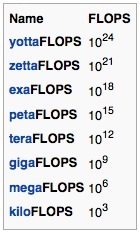
MIPS - Millions instructions per second
DFLOP - D stands for ten (DECA)
HFLOP - H stands for hundred (HECTO)
KFLOP - K stands for thousand (KILO)
MFLOP - M stands for million (MEGA)
GFLOP - G stands for billion (GIGA)
TFLOP - T stands for trillion (TERA)
13,600 MIPs is 13,600,000,000 IPS or 13.6 billion instructions per second, related to 13.6 GFLOPs. In going from 5 chips to 100: 20x13.6=272 GFLOPS.*
* Note this is a relative theoretical comparison from one Propeller chip to a series of Propellers within the contextual definitions we have established for one chip, and is not intended as a comparison to other machines with other designs.
LINKS
Spin Brain
Supertronic Spin Brain
FLOPS
Parallax
Propeller Info
Propeller Chip
PROPELLER SPIN BRAIN PART 2
"The Spinning Brain"
Continuing with our previous edition about the Spin Brain, we will look at five Parallax Propeller chips connected together to make a new type of processing machine, examining more elements and specs about this cute little machine.
In this Edition of The Spinning Brain, we will cover
- 5 Chip Inventory
- Processors
- Speed Units
- Related Links
CHIP INVENTORY
Five chips provide for the following useful elements of functional inventory:
5 Chip Inventory
* Five AI individuals (5 chips)
* 40 Deterministic Cores (5x8 Cogs)
* 160 GPIO Pins (5x32)
* 160K RAM (5x32K)
* 160K ROM (5x32)
* 80 Counters (5x16)
* 40 Video Generators (5x8)
* 13,600 MIPS (5x2720 Theoretical)*
* 160 Hard Processors (5x32)
* 5,000 Vprocessors (5x1,000)
* 5,160 Total Processors (5,000+160)
* SPIN, PASM Programming Languages
PROCESSORS
Each Cog is a RISC processor and each chip has eight. Each counter is a processor with exactly one instruction: a conditional ADD. A chip has 16 counters. Each video generator is a processor with one instruction: a Shift by one or two. A chip has eight video generators.
Processors per Chip
08 Cogs
16 Counters
08 Video Generators
32 Total Processors per chip
SPEED UNITS
MIPS - Millions instructions per second
DFLOP - D stands for ten (DECA)
HFLOP - H stands for hundred (HECTO)
KFLOP - K stands for thousand (KILO)
MFLOP - M stands for million (MEGA)
GFLOP - G stands for billion (GIGA)
TFLOP - T stands for trillion (TERA)
13,600 MIPs is 13,600,000,000 IPS or 13.6 billion instructions per second, related to 13.6 GFLOPs. In going from 5 chips to 100: 20x13.6=272 GFLOPS.*
* Note this is a relative theoretical comparison from one Propeller chip to a series of Propellers within the contextual definitions we have established for one chip, and is not intended as a comparison to other machines with other designs.
LINKS
Spin Brain
Supertronic Spin Brain
FLOPS
Parallax
Propeller Info
Propeller Chip
Wednesday, June 26, 2013
Supertronic Spin Brain
![]() |
| Standard Propeller chip specs |
The Supertronic Spin Brain is a regular Spin Brain made Supertronic. Supertronic enhances each Parallax Propeller chip to a higher speed level and more processors.
The following lists shows specs for the standard Spin Brain and the new Supertronic Spin Brain. The Supertronic Spin Brain is 13.6 times faster and has 472 more processors in the maxed config. Cores (Cogs), GPIO, RAM/ROM, VProc, and cost remains the same. The Standard Spin Brain programs will run on the Supertronic Spin Brain, and the new commands of the Supertronic Spin Brain will run on the Standard Spin Brain when configured to do so.
Standard Spin Brain Overclocked 200MIPs/Chip
Prop Cost Core VProc Total MIPS GPIO RAM/ROM(K)
001 $008 008 001000 001008 00200 0032 000064
002 $016 016 002000 002016 00400 0064 000128
003 $024 024 003000 003024 00600 0096 000256
004 $032 032 004000 004032 00800 0128 000512
005 $040 040 005000 005040 01000 0160 001024
010 $080 080 010000 010080 10000 0320 010240
100 $800 800 100000 100800 20000 3200 102400
Supertronic Spin Brain
Prop Cost Core VProc Total MIPS GPIO RAM/ROM(K)
001 $008 0032 001000 001032 002720 0032 000064
002 $016 0064 002000 002064 005740 0064 000128
003 $024 0096 003000 003128 008160 0096 000256
004 $032 0128 004000 004256 010880 0128 000512
005 $040 0160 005000 005512 013600 0160 001024
010 $080 0320 010000 010320 027200 0320 010240
100 $800 3200 100000 103200 272000 3200 102400
Subscribe to:
Posts (Atom)