Monday, December 23, 2013

FM Radio Station Part 3 Assembly & Tips

Fully assembled and ready for testing, the FM transmitter radio station is shown with a potential cabinet housing. Note how the microphone is repositioned top side for ease of positioning inside and through the yellow cabinet.
assembly and tips
HOW TO BUILD YOUR OWN FM RADIO STATION TRANSMITTER PART 3

PARTY TIME!!! Today is a solder party. Get out your guns (soldering guns) and prepare to melt some metal, putting metal (tin) on metal (copper).

Tuning the frequency
By a bit of trial and error plus observation with a nearby FM radio receiver, it is possible to tune the FM transmitter. Using the coil, either expand or compress the wire coils to change the frequency. A closer wire gap give a lower frequency and a loose wider spacing gap gives a higher frequency.

The completed solder side of the printed circuit board with a green loop antenna about 2.75-inches high and a microphone set outwards on one side to facilitate a good fit through the cabinet top. Prime use of this project is to fulfill the authors objective to own and operate a tiny radio station (at the toy level) - in this case, a tiny exampling FM band transmitter that can send broadcasting from one side of the table to the other side.

Apps won't end there as the transmitter can have audio signal input into its stage, such as a Parallax Propeller chip's voice speech synthesizer signal inside the electric brain in a jar, and then transmit a speech signal through the jar, speaking wireless into a nearby radio. Building one transmitter is very cost effective at US$4.
When soldering the electrolytic capacitors and the transistors, use a heat sink on each of the wire leads to prevent component damage from heat.

It is also possible to change the value of the ceramic capacitor which is in parallel with the coil. Some designs use a tunable variable capacitor to do the tuning. In this case, the variable capacitor would have a tunable range from 0 to 10 pF. Since this transmitter has no requirements for specific FM frequencies, the variable capacitor is not needed.

Experiment with the coil spacing first to determine the range. Keep the receiver at distance from the transmitter to minimize the reception of spurious radio signals. Make sure you've found the primary signal which will have the greatest signal strength.

Reference this image showing a different orientation for clarity, to the photo in post part number 2 for circuit path positions. Note the coil spacing to change the frequency to a "quiet spot" on the upper FM dial.
The 10 pF capacitor is set to match the number of turns on the coil. With a greater capacitor value such as 20 or 50, the number of coil turns would be too much.

Antenna Length
First, here are some "getting started" approximate values already calculated for some frequencies. A full wave antenna for 98 Mhz, the center of the FM band, would be 119 inches. A half wave would be 59 inches. A quarter wave antenna for 98 Mhz would be 29 inches long. Try an eighth wave antenna at 14 inches long or a sixteenth wave antenna at 7 inches.

Online Whip Antenna Calculator
http://www.csgnetwork.com/antennagenericfreqlencalc.html
For more precise values, enter the frequency and the online program will calculate half and quarter wavelength whip antenna size. Requires browsers with enabled Javascript. "This calculator is designed to give the vertical length (height) of a particular whip type antenna, or the frequency of it. Enter one (only one) value, the desired frequency or the antenna length in any length field. Click on Calculate and the opposite value will be displayed in feet and inches or frequency in megahertz (Mhz). These are considered as generic calculations and you may wish to use them to learn general information about the antenna structure you are contemplating. Click on Clear Values to prepare for new calculations. Any antenna created with this calculator MUST be fine tuned for VSWR. None of the calculations are rounded or massaged and all calculated results are raw data."

Frequency Stability
The frequency may drift as the battery voltage becomes less. This is expected with this simple design. To offer more regulation, one could use a regulated power supply instead of the battery. The simple design presented here for exampling will use fresh batteries and some frequency drift will be expected. Do not use an AC adapter as these are generally not regulated and introduce interference.

Use with iPod, iPhone, iPad
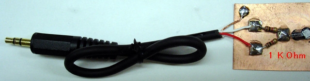
"The earlier model of iPod has an automatic shut-down system in it. When you pull out the plug of your headphone, it automatically stops working. When the left and right channels are short-circuited, the same thing happens. Presumably, you can use a stereo cable and solder the left (white) and right (red) lead together. Please use the left channel lead (white) only. Usually the left output is compatible with mono audio. If you, however, insist to mix the left and right output of your audio source into the transmitter, make a simple "interface" like this." Source: http://www.translocal.jp/radio/micro/howtosimplestTX.html

Radio Station Parts List
1 Resistor 820 Ohm
1 Resistor 4.7 K
1 Resistor 3.3K
1 Resistor 10K
1 Resistor 220K
1 Resistor 1K
1 Capacitor Ceramic Disc 10 pF
1 Capacitor Ceramic Disc .001 uF (102)
1 Capacitor Ceramic Disc .01 uF (103)
2 Capacitor Electrolytic 4.7 uF
1 Transistor 2SC1675 (or 2SC829) Q1
1 Transistor CS9013 Q2
1 Antenna Wire 16"
1 Coil (see text)
1 Electret Microphone
1 Printed Circuit Board
1 Enclosure
1 Printed Panel

Although controls are not necessary, adding a power switch and other capabilities may be desirable.

Spartan Version
On/Off Switch
A very spartan version with rudimentary controls is possible by using a rectangular project box with a hole for the mic protrusion and a hole for the on/off battery switch.

Basic Three Version
On/Off Switch
On the Air LED
Mute Switch
The on/off is a toggle switch wired to turn the 9 volt battery supply on or off.

The next upgrade can include a red LED for "on the air" monitor. This would wire in with the on/off switch and a dropping resistor to the LED.

Another handy feature is an audible mute switch. This would cut out the microphone and switch to a resistor with the same resistance as the microphone.

Deluxe Version
On/Off Switch
On the Air Red LED
Mic Mute
Variable Volume Control
External Sound Input
Signal Strength
Amplifier Monitor
Headset for Amp Monitor
External Power Supply
Switch from 3V, 6V, 9V (regulates output power)
2 Sound Source Mixer
External Antenna 1 or 2 

Band - With different switchable "band" coils, it would be possible to change the transmitting frequency.

Trim - With a variable 0 to 20 pF capacitor, it would be possible to tune the transmitting frequency.

Clock - with added processor
Compass - with added processor

SOURCES
http://www.translocal.jp/radio/micro/howtosimplestTX.html

FM Radio Station Part 5 Index
http://humanoidolabs.blogspot.tw/2013/12/fm-radio-station-part-5-index.html 

Sunday, December 22, 2013

FM Radio Station Part 2 Assembly

Flipped reverse side photo to match component side
MINI FM RADIO STATION  Note top side component placement. Top two holes are for the 9-volt battery clip leads with ground on the left side. The left bottom hole and the bottom right hole are for the antenna connection.
Connections are easily seen when the printed circuit board is back lit, showing the circuit board traces on the reverse side. This makes it easier to match component locations to the schematic diagram.
Schematic diagram for a two stage transistor FM transmitter. Features microphone driven audio input, with tunable frequency range with L1. Operates on a 9-volt battery. Range tests are yet to be determined but the frequency appears to be around 100MHz on the FM band.
BUILD YOUR OWN FM RADIO STATION TRANSMITTER
IN-HOUSE DIY RADIO STATION PART 2


Rotated left to right view for component placement


Work is progressing on the electronic construction of the Lab's two stage exampling FM radio station. Stay tuned to this series of blogs as we supply the details of going on the air, as well as technical info so you can roll your own in-house radio station for fun.

The test transmitter printed circuit board has 17 components mounted and ready for soldering. This blog details the component placement and the circuit traces on the printed circuit board and includes transistor placement guides and a schematic for assembly. Note the two transistor identifications in the illustration showing keyed emitter, base and collector locations. 

The power board uses two transistors, a C1675 K6YC at the right side of the board (see photo above) and a C9013 H049 nearest the microphone. The circuit has one electret microphone input for voice operations and includes one coil, two transistors, two electrolytic capacitors, five ceramic disc capacitors, and five resistors. Not shown is a 9-volt battery clip and the antenna.
Verified leg identification ok
The antenna is only a few inches of wire which minimizes the range for initial testing, and limits use and range of reception to inside the lab room. The electronic project goal is an exampling in-house educational fully functional radio station. More tests will determine the range characteristics more precisely.
Note that some countries and municipalities allow short range transmitters of this type and some do not. Be sure to first check local laws and regulations before proceeding with the project.

The copper printed circuit side of the board with through hole leads ready for hot soldering
Ok to Use: MICRO Data/Japan data
The coil in combination with the parallel capacitor tunes the circuit to a frequency within the FM band.

Frequency trimming is accomplished by stretching or compressing the coil or modifying the value of the ceramic parallel 10 pF capacitor.

Initially the frequency should be in the range of 88 to 108 mHz on the FM band.

Warning - do NOT use USHA India/LGE leg positions
The radio station will have an identical twin backup system for service or parts to remain up and running as necessary.

The cost of the first set of parts is NT$132 (US$4.42) and the backup duplicate parts are NT$120 (US$4.00). Thus far, combined cost is US$8.42 for the hardware.

The transistor leg identification does not agree from one data sheet to the next. See diagrams.

Careful with data sheets for the 2sc1675 transistor as there are discrepancies between the TO92 and TO92b case versions. For example, the equivalent Panasonic 2sc 829 equal to 2sc 1675 as a substitute is in agreement with the transistor placement of emitter, collector, base, therefore this is the arrangement to use.

FM Radio Station Part 5 Index
http://humanoidolabs.blogspot.tw/2013/12/fm-radio-station-part-5-index.html

Friday, December 20, 2013

FM Radio Station Part 1 Announcement

Preliminary Radio Station Design
FM RADIO STATION TRANSMITTER
PART 1 ANNOUNCEMENT
Coming to a station near you!

The Big Brain machine is developing a radio station for programs dealing with Big Brain topics and schedules. Programming detail is yet to be determined as the design of the station is in the works.

It could include the sounds of the local SETI program, downloadable serial sounds for direct reception of Parallax Propeller chip software, special music, details of the powerful telescopes observing schedules at the Humanoido Observatory, Lab schedules and updates, various projects, educational programs, ESL language programs, special weather reports, planet and solar casts, Brain Cortex news, etc.

The science Laboratory station includes a fully electronic radio station transmitter capable of reaching your home if your location is within the range of the electromagnetic signal.

Scheduling
Programming schedules may appear in this blogger ahead of time, and transcripts may be available before or after the broadcasts. There is always the surprise and unannounced broadcast with special information.

It is not determined if the Big Brain machine will narrate all or many of the broadcasts and programs using its machine voice.

The idea for the station was hatched long ago, and now resources are available to make it happen. The location sites of the transmitters are currently undisclosed. Stay tuned for more information.

Web Version
Along with the radio version, a web version radio may appear for those individuals not within the electromagnetic signal range. A static web version could feed text transcripts of various broadcast programs about science and technology.

FM Radio Station Part 5 Index
http://humanoidolabs.blogspot.tw/2013/12/fm-radio-station-part-5-index.html

Wednesday, December 18, 2013

Brain Cortex Jar Study Part 54

BRAIN CORTEX In the forth corridor, the spirit thermometer bisects the compartment making space for dual desiccators at this location. The jar has three remaining full size dessication compartments created by the corners of mounted power units. The jar study verifies the necessity of a sizable desiccation system. After the jar is hermetically sealed, RH will settle although the temperature may fluctuate based on the external temperature variance and heat given off by the internal energy source.
BRAIN CORTEX JAR STUDY PART 54
As work progresses on the construction of a brain in a jar and electric devices are coming together, experiments are conducted on the atmosphere occurring inside the jar.

With the jar kept a bit ajar on the lid, the temperature and humidity are monitored without the Desiccator Unit in place. As the temperature drops below 70 degrees Fahrenheit, we see the RH shooting up to 65 without any indoor climate control in place.

High levels of humidity are to be avoided inside the jar to prevent any surface sweating condensation and resulting corrosion, and as a result of this study, the jar will received a Quad Desiccator to bring down RH.

It's recommended to keep the jar sealed, activate the QD, and monitor the internal temperature particularly during charging to prevent any overheating conditions.

Desiccators can be removed for dessication recharging, by removing heat safe chemical crystals in the container and baking the contents on a metal pan in an oven to remove their moisture content. Instructions are on the web and follow all safety precautions.

The QD will reside in the four remaining corners produced by mounting the Power Units. In the fourth containment, a space bisection results leaving two narrow vertical corridors which are perfect for mounting cylindrical desiccators, one one each side of the spirit thermometer.

The QD is currently under construction, mainly involving a large collection of the dessication chemical. The dessication chemical is free by scrounging assorted sources and packaging.

Tuesday, December 17, 2013

Mini Space Shuttle

Mini Shuttle smaller than the X37
BIG MACHINE BRAIN SUGGESTS MINI SPACE SHUTTLE CONSTRUCT
Overall design with cargo bay
Big enough to ferry an astronaut and supplies, small enough for space hoisting by private industry...

We're not sure why the electric machine Big Brain wants one of these. Perhaps it's to carry up a space telescope and parts, to study new machines in space, to assemble something, help save the Earth, rescue an astronaut, act as a life boat for the ISS Space Station, or make trips to the Moon.

The illustrative design is originally based on the X-37 from NASA and the recent X-37b from the USA Air Force. While the X37b is secretive, the proposed mini shuttle would operate for the Big Brain directive. The proposed MS would be substantially smaller than depicted here.

Of course the Experiment bay would be outfitted with astronaut seating, the control panel would be designed for a pilot, and supplies would stow under the seating.

Reentry with fire resistant fabric
The craft would have gliding capabilities during reentry and landing. The Mini Shuttle MS could visit space by riding in the cargo bay of larger rockets and return under its own capability.

Suggestions for enhancing the mini space shuttle craft include solar panels for extended stays in
Docking with the Space Station
space, small size for fit into rocket nose cone, light weight for minimal launch cost, hatch and payload bay doors for space walks/ mini satellite deployments/ observations with a space telescope and storage for extended stays in space (food, water, toilet packaging and ejection system) and air
Equipped for passengers
re-pressurization system for visiting and docking with other spacecraft, space stations, and space hotels.


Deploying solar panels
One design suggestion for the reusable space craft is a heat resistant replaceable fabric for fiery reentries into the Earth's atmosphere. Also the craft could orbit the Moon, observe through telescopes, and deploy tiny satellites and landers to the surface. The MS could also leave behind mini orbiters with capability of telescopes, radio transponders and relay stations.

Another design is for rescue. Maneuvering thrusters enable the craft to go to retrieve an astronaut flung out into space
One pilot
from the space station or other ship or retrieve an astronaut from an error in a space walk. In case of emergency, an astronaut from the space station could space walk to the mini shuttle and return to the Earth. The two passenger seats collapse flat to carry one injured or sick person. The craft could hold three, one of which is the pilot.

It's also determined the craft space could be configured the same size as a small Japanese or Chinese apartment with all spartan yet efficient amenities for longer stays living in space. The craft could also conduct limited space tours of orbital Earth and the Moon, plus offer spectacular sky views in space for not only tourism but scientific research.

Astronaut EVA out of the mini shuttle
LINKS
http://www.nasaspaceflight.com/2013/03/x-37b-expanded-capabilities-iss-missions/


Photo Credits: NASA,
iTunes APP Astronaut Spacewalk by Jorge Hernandez
https://itunes.apple.com/app/astronaut-spacewalk/id540221533?mt=8

Dream Chaser concept
Is the mini shuttle already built in the form of dream chaser? Read more at the links.

http://www.nasaspaceflight.com/2013/12/dream-chaser-ccdev-2-green-light-nasa/

http://www.nasaspaceflight.com/2012/08/dream-chaser-space-shuttles-legacy-advantage/

http://www.nasaspaceflight.com/2012/08/nasa-ccicap-funding-spacex-boeing-sncs-crew-vehicles/

It's possible to send up one astronaut specifically as a systems specialist to repair space equipment when a mini space shuttle is in operation. Astronaut Rick Mastracchio is shown space walking outside the ISS International Space Station. Credit: NASA
"Dream Chaser – which is a reusable lifting body vehicle based on the form of NASA Langley’s HL-20 spaceplane concept from the 1980s – can land on a conventional runway, unlike all of its capsule-based competitors. The plan is for Dream Chaser to land at the Shuttle Landing Facility (SLF) at KSC." NASA

The Dream Chaser is a crewed suborbital and orbital[7] vertical-takeoff, horizontal-landing (VTHL) lifting-body spaceplane being developed by Sierra Nevada Corporation (SNC) Space Systems. The Dream Chaser is designed to carry up to seven people to and from low Earth orbit. The vehicle would launch vertically on an Atlas V rocket and land horizontally on conventional runways. Wikipedia
http://en.wikipedia.org/wiki/Dream_Chaser

Extremely Powerful Telescope Functions

GUIDE TO EXTREMELY POWERFUL TELESCOPES & FUNCTIONS

These telescopes are above and beyond all previous telescopes prior to the extremely powerful telescopes series. These telescopes have made more discoveries and innovations than all the previous telescopes combined. The EPT series is expanding new science and technology and paving the way through and beyond the Universe.

MAIN FUNCTIONS OF EACH TELESCOPE WITH LINKS
1) ULT Ultra Large Telescope 
Feb 27, 2012, Aperture 24-meters, Features: Symbiotic Earth-Space Telescope, Mobile to change positions in the solar system, UP Universe Penetrator, MMS Multi Mag Slider, 94 swarming Adjuctive Arrays, 724 processors. Discoveries: Found Saturnian Rocks, Discovered Multi Storms inside the GRS, Ultra Deep Imaging, Penetration to over 13 Billion Light Years, Near the Edge of the Universe Boundary (EOU), Penetrated the Globular Stellar Abyss, the Farthest Two Galaxies at the Edge of the Universe, Deepest Galactic Penetration into 2.6 Million LY Zone, Planet Outside Our Solar System, Pluto Detail Imaging, Multi-Meter Lunar Res with Lunar Adjunctive, Experimental, Inventive, Exploratory, Breaking New Technology, Relatively Easy to Use, Big Brain Enabled

032012 Telescope Arm Reaches for End of the Universe (Blockage)
http://humanoidolabs.blogspot.tw/2012/03/telescope-arm-reaches-for-end-of.html
032412 ULT Coldest Place in the Universe

http://humanoidolabs.blogspot.tw/2012/03/ult-coldest-place-in-universe.html
032812 ULT Saturn Rings Journey

http://humanoidolabs.blogspot.tw/2012/03/ult-saturn-rings-journey.html
032812 ULT Increase in Size & Resolution (Star Test)

http://humanoidolabs.blogspot.tw/2012/03/big-brain-increases-ult-resolution.html
032912 ULT Deep Stellar Abyss Reveal

http://humanoidolabs.blogspot.tw/2012/03/blog-post.html
033012 ULT Sun Flare

http://humanoidolabs.blogspot.tw/2012/03/ult-sun-flare.html

2) NULT New Ultra Large Telescope
http://humanoidolabs.blogspot.tw/2012/02/penetrator_27.html
First Light March 27th, 2012 (farthest known galaxy in the Universe). Aperture 945-inch. Features: Big Brain Penetrator, 101,500 processors, Higher Resolution, greater storage, New Accumulator and HUD Heads Up Display, Adjunctive Array & Repeatability, Can be in multiple places at the same time, super computer driven, Discoveries:
022712 Galaxies at the Edge of the Universe

http://humanoidolabs.blogspot.tw/2012/02/penetrator_27.html
030112 Black Hole

http://humanoidolabs.blogspot.tw/2012/03/black-hole-found.html
030212 Andromeda Galaxy

http://humanoidolabs.blogspot.tw/2012/03/nult-andromeda.html
030312 Lunar Rover

http://humanoidolabs.blogspot.tw/2012/03/nult-telescope-lunar-rover.html
030412 Kepler 22B

http://humanoidolabs.blogspot.tw/2012/03/nult-kepler-22b.html
030512 Jupiter Great Red Spot GRS

http://humanoidolabs.blogspot.tw/2012/03/nult-telescope-jupiter-great-red-spot.html
030712 Pluto

http://humanoidolabs.blogspot.tw/2012/03/nult-telescope-pluto.html

3) GT Genius Telescope
http://humanoidolabs.blogspot.tw/2012/06/gt-genius-telescope.html
http://humanoidolabs.blogspot.tw/2012/06/gt-telescope-venus-transit-first-light.html
First Light June 6th, 2012 (Transit of Venus). Aperture(s) 1.5-mile, 15-miles, 150-miles. Features: TMA Tri Mode Aperture, VARUP Variable Universe Penetrator, FUP Factorial Universe Penetrator, Expanded Adjunctive Multiple Array, GTA Genius Telescope Accumulator, HUD Heads Up Display, Location Entanglement, Discoveries:

June 8, 2012 GT Telescope Venus Transit First Light 
http://humanoidolabs.blogspot.tw/2012/06/gt-telescope-venus-transit-first-light.html
July 13th, 2012 Sun Edge Reveal
http://humanoidolabs.blogspot.tw/2012/07/suns-edge-reveal.html
September 9th, 2012 Black Hole Event Horizon
http://humanoidolabs.blogspot.tw/2012/09/black-hole-event-horizon.html

4) PGT Paradigmic Genius Telescope
http://humanoidolabs.blogspot.tw/2012/09/paradigmic-gt-telescope.html
First Light Sept. 10th, 2012. Aperture 7,000 miles. Features: MAC Multiple Adjunctive Concatenation, Molecular Stage Cascader, CSW Character Selection Wavelength, Interferometry. Discoveries:

101512 M42 Orion Nebula
http://humanoidolabs.blogspot.tw/2012/10/m42-pgt-paradigmic-genius-telescope.html

5) MGT Molecular Genius Telescope

http://humanoidolabs.blogspot.tw/2012/10/big-brains-new-paradigmic-molecular.html October 17th, 2012. Aperture: Enhanced PGT to over 7,000 miles. Features: Interim Testing Scope, MAC Molecular Amp Cascader & Processor, Pipe Fitting Atop the PGT Telescope, Transformation Telescope from PGT to PGT-ET

6) PGT-ET Paradigmic Genius Telescope Enhanced Technology
http://humanoidolabs.blogspot.tw/2013/03/pgt-telescope-new-look.html
First Light March 30th 2013. Aperture: Width of the Solar System 7.5 billion miles. Features: GMM Molecular Processor, 70 New Advanced Controls, Extracted Parasitic Functions, Electronic Lens Booster, Analyzer Head. Discoveries: Mars Volcano Olympus Mons
http://humanoidolabs.blogspot.tw/2013/04/pgt-et-telescope-mars-mt-olympus.html
The Edge of the Universe
http://humanoidolabs.blogspot.tw/2013/04/pgt-et-telescope-edge-of-universe.html
Dragon Head Nebula
http://humanoidolabs.blogspot.tw/2013/04/pgt-et-telescope-dragon-head.html
New Stars
http://humanoidolabs.blogspot.tw/2013/04/pgt-et-telescope-stars.html
Ring Nebula Cosmic Striations
http://humanoidolabs.blogspot.tw/2013/04/pgt-et-v.html
Crab Nebula
http://humanoidolabs.blogspot.tw/2013/04/pgt-et-test.html

7) PDT Power Dynamic Telescope Explorer Class
http://humanoidolabs.blogspot.tw/2013/04/power-dynamic-telescope-first-light.html
First Light April 21st, 2013 (Gravitational Black Hole), Aperture: 9 billion miles. Features: Morphable Configuration Array Telescope, 142 Advanced controls
http://humanoidolabs.blogspot.tw/2013/04/power-dynamic-telescope-updated-controls.html
Electric Barlow Enhancement, FORE Focalization Reductor, SUM of all previous Adjunctive telescopes and the GMM Molecular Microscope. Discoveries:
Pinpointing a Singularity
http://humanoidolabs.blogspot.tw/2013/05/pinpointing-singularity.html
Two Edges Universe
http://humanoidolabs.blogspot.tw/2013/05/two-edges-universe-unfolding.html
Black Hole Floaters and Red Matter
http://humanoidolabs.blogspot.tw/2013/04/black-hole-floaters.html
Strange Object Inside Black Hole
http://humanoidolabs.blogspot.tw/2013/04/object-inside-black-hole.html
Black Hole Contort Space
http://humanoidolabs.blogspot.tw/2013/04/black-hole-heart.html
Through the Center of the Ring Nebula
http://humanoidolabs.blogspot.tw/2013/04/power-dynamic-telescope-pdt-through.html
Resolution of Red Super Giant Star
http://humanoidolabs.blogspot.tw/2013/04/power-dynamic-telescope-pdt-sees-syper.html
Journey to a Gravitational Black Hole
http://humanoidolabs.blogspot.tw/2013/04/power-dynamic-telescope-first-light.html


8) GGT Gargantuan Gravatomic Telescope
http://humanoidolabs.blogspot.tw/2013/05/next-telescope.html  
May 6th, 2013 Introduced, Aperture: Possible Interfero-Gravitometric diameter to the edge of the Universe exceeding width of Solar System. Number of Controls: est 200 - see PDT list plus additions. Features: 1st Gravatomic Telescope. Discoveries: Melting time & space
GGT Gargantuan Gravatomic Telescope
First Light GGT Gargantuan GravAtomic Telescope
Gravatomic Machine
Age of Gravatomic
GGT Faceplate Control Icon Rework
Telescope Icons
Meltdown of Space & Time 


9) SRT - Space Recycler Telescope
http://humanoidolabs.blogspot.tw/2013/05/novel-space-junk-telescope.html

The SRT generally uses one Adjunct and its data sets are more time dependent. The telescope can focus attention on what to observe and when to observe. This SRT is the most simple telescope in the series - and it's powerful as it can have an aperture diameter exceeding the largest Earth-based telescopes. It has the most basic controls and the most simple methodology of  operations. To keep things simple, telescope linking is unary and the process of data mining is fundamental. Refer to the Face Plate showing control icons. Cutting edge work: the Planet Saturn
Space Recycler Telescope SRT
 

10) MMT - Molecular Mining Telescope 
http://humanoidolabs.blogspot.tw/2013/05/mgt-molecular-cradle-of-stars.html
May 20th, 2013. The new MMT Molecular Mining Telescope is now dedicated to Molecular mining of the Universe and beyond. The idea to pipe mount the Molecular Device from the GMM Genius Molecular Microscope onto the GT Genius Telescope was one of the best ideas in the Big Brain's Space Initiative. This led to Mining in the Universe with a new kind of molecular mode, which has revealed spectacular results and many new discoveries, providing a high level of exploration and continued discovery. The MMT telescope is configured with several key features: Adventure and Explorer Class Modes, Molecular Device, Adjunctive, Genius, Supercomputer, ET Enhanced Technology, Paradigmic and Power Dynamic.
MMT Molecular Mining Telescope Horsehead Nebula
MMT Molecular Mining the Cradle of Stars


11) IET - Inference Engine Telescope
http://humanoidolabs.blogspot.tw/2013/05/iet-interference-engine-telescope-first.html
May 20th, 2013. The IET is a full scale Expert Forward Inference Engine telescope. First Light imaged inside a Black Hole. New discoveries: 1) Perimeter Molecular Energy Spicules, 2) Lenticular Distributed Elliptical Energy, 3) Nodal Matter Rings. The IET primary feature: Expert Forward Inference Engine, offers elements of idea, creativity, vision, innovation, reasoning, interpolation, extrapolation, etc. The telescope's Engine can explore the 6th dimensional element of Imagination Power. No other telescope has this function. In Quantum Physics, the act of observing and thinking about something can effect and alter it significantly. The outward execution of imagination may directly or indirectly involve in affection of some types of matter, space, time, and/or reality. The Expert Inference Engine is ideally poised to continue such experiments and missions and has led to studies of Altercated-Alternated Reality.
IET Inference Engine Telescope First Light
IET Inference Engine Telescope Construction
New Expert Inference Engine
Inference Engine Icon


12) M3T Massive Molecular Mining Telescope
http://humanoidolabs.blogspot.tw/2013/11/m3t-telescope-first-light-saturn.htmlThe new Massive Molecular Mining Telescope, the 12th telescope addition to the extremely powerful telescope array, has the largest Power Dynamic Face Plate ever created (as of 11.27.13). This telescope is known as M3T. First Light on Tuesday November 26th, 2013 focused on the planet Saturn. A glorious ring system appeared through the amplified molecular particle dynamic quanta. The intent was to image the spherical globe through rings, however the emergence of the reveal showed far more discoveries than expected.

New tenuous rings appeared outside and inside the system as well as the Saturnian globe was shining through and in between specific rings. This represents new RS discoveries and a new ring count including new rings both inside and outside the previously known Saturnian ring system.


13) ET - Extrapolation Telescope - December 2013
http://humanoidolabs.blogspot.tw/2013/12/et-telescope.html

14) IT - Interpolation Telescope - December 2013
http://humanoidolabs.blogspot.tw/2013/12/it-interpolation-telescope.html  


15) OT - Over the Top Telescope - January 2014
http://humanoidolabs.blogspot.tw/2013/12/ott-over-top-telescope.html

Earlier in the year, the OT Telescope was the unknown super powerful telescope with initial speculation: This super powerful telescope may have pipe fitting alliance with the Altercated-Alternated Reality Machine (AAR Machine) and other space machines, however details are unknown at this time. In reality, the OT takes on the functions of all the previous extremely powerful telescopes, making combinations that are mind boggling in terms of new discoveries possible.
Altercated Alternated Reality Machine
Generating Altercated Alternated Reality